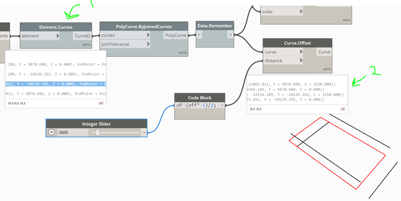
Any idea why Curve.Offset (2) offsetting Z on two of the lines but not the others?
In Element.Curves (1) ALL the Z coords are 0 and all the Z vectors are 0
Any idea why Curve.Offset (2) offsetting Z on two of the lines but not the others?
In Element.Curves (1) ALL the Z coords are 0 and all the Z vectors are 0
I’ve no idea to why it does that!
Probaby @GavinNicholls can help us out since I feel he is really good when it comes to geometry.
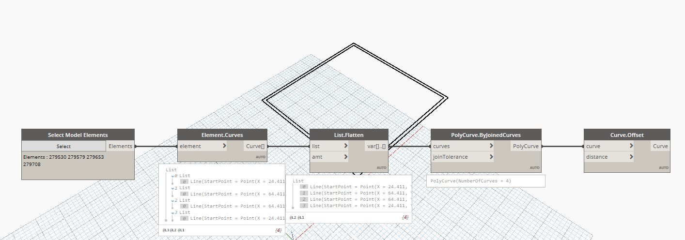
But in case if you want the desired output, you can flatten your list before it enters the PolyCurve node.
Thanks!
I swapped my normal lines for a boundary line in Revit and that worked too.
Still would like to know though if anyone has an idea 
The curves are offset within their existing plane. Some of the elements you pulled curves from were not in the XY plane.
I don’t understand.
All Z numbers were 0 so doesn’t that make them in the XY plane only?
I took the elements from a rectangle (detail lines) in Revit all at the same Z coordinate which was zero.
Best way to learn this is to break this down into reality world’ examples.
Almost all geometry in Revit is based on a work plane as the ‘host’. The plane could be a level, a view, a grid, a reference plane, or the face of an existing piece of geometry. Your geometry then has a coordinate system based on that plane.
OK - but I drew the rectangle using a detail line and a rectangle tool.
How can 2 sides be in a different plane from the other two sides?
[0] Line(StartPoint = Point(X = 15675.147, Y = 11956.953, Z = 0.000), EndPoint = Point(X = 15675.147, Y = -12743.047, Z = 0.000), Direction = Vector(X = 0.000, Y = -24700.000, Z = 0.000, Length = 24700.000))
[1] Line(StartPoint = Point(X = 15675.147, Y = -12743.047, Z = 0.000), EndPoint = Point(X = -12324.853, Y = -12743.047, Z = 0.000), Direction = Vector(X = -28000.000, Y = 0.000, Z = 0.000, Length = 28000.000))
[2] Line(StartPoint = Point(X = -12324.853, Y = -12743.047, Z = 0.000), EndPoint = Point(X = -12324.853, Y = 11956.953, Z = 0.000), Direction = Vector(X = 0.000, Y = 24700.000, Z = 0.000, Length = 24700.000))
[3] Line(StartPoint = Point(X = -12324.853, Y = 11956.953, Z = 0.000), EndPoint = Point(X = 15675.147, Y = 11956.953, Z = 0.000), Direction = Vector(X = 28000.000, Y = 0.000, Z = 0.000, Length = 28000.000))
The lines are on the same plane surely?
What am I missing?
To follow @jacob.small’s paper analogy…
If the paper represents the local XY Plane and the table represents the global XY Plane (Z=0), then holding the paper 6" off the table does not mean that the paper is no longer an XY Plane. It just means that the local XY Plane now has a Z coordinate of 6.
OK. I understand that. But surely the lines drawn using the rectangle tool in Revit all have the same Z plane?
So why do two of them offset on the Z plane but the other two don’t?
Was the rectangle drawn in a drafting view?
All this isn’t to say that something weird isn’t going on. It does seem odd that a rectangle drawn in a view would put lines on different local planes. But logically there are reasons this could happen.
I would expect a rectangle in a drafting view to be on the same plane. A model view could be different. I’m guessing that the normal plane for each curve varies based on the direction it’s drawn.
The original rectangle in Revit was drawn in a floor plan view.
It came into dynamo as a rectangle (I looked from all angles).
The offset however gave two of the lines (the parallel shorter ends) a Z coordinate other than 0 while the other two (longer opposite sides) remained on the same Z coordinate as the original rectangle.
I re-drew my Revit rectangle using a property line and the offset now works.
I could definitely see lines drawn in a model view being placed on planes dependent on the direction they’re drawn. This is pretty common for most elements. Combining them into a polycurve like was recommended is the best way to make sure they’re all planar.
This makes sense to me because property lines have to be drawn on the XY Plane so they will always have the same “orientation”. Even though we think of detail lines as 2-dimensional they maintain 3D properties.
If you look at the script I posted I did that. The original rectangle was fine. It’s the offset.
Very odd!
Also bear in mind my original Revit rectangle was click click (using the rectangle tool, not 4 separate lines in a chain)… so how could the Z axis be different for two of the lines?
Oh, I didn’t realise they’d have any 3D properties at all.
What’s the logic behind that do you know?
Thanks for the replies btw guys even if it’s still a mystery 
As @AmolShah said, you’ll need to flatten the list of curves before combining them into a polycurve. Right now you’re turning your 4 separate lines into 4 separate polycurves, which isn’t really doing anything. You want 1 combined polycurve to offset.
Revit still has to draw 4 separate lines. The Z-coordinate values for the lines don’t differ, but the planes they exist on do. Again, my guess is that it’s based on the direction the lines are drawn.
Everything has 3D properties even if some of those properties are locked out of one plane. I’m guessing detail lines keeps some of these properties because they can be converted into model lines.
What is the ‘host’ of the item you clicked on to draw the line? It’s VERY easy to associate content to a differing work plane. This is by design to make tools like the ‘pick line’ work effectively without throwing many ‘not on plane’ errors.
You will find a great many ‘oh I didn’t realize Revit did THAT’ moments as you get further and further into computational geometry within the Revit framework. Sadly as an application which does ‘everything’ pretty well it means the ‘oddities’ are frequent rather than rare.
It was a blank canvas. The view was a level 0 floor plan.
I used a detail line and the rectangle tool.
I also tried it again using the line tool and drew a chain.
Both reproduced the same result. 
I mean tbh, I can use something else so it’s not an issue but I am interested in why .