Hey guys, I need some help with this. I’m trying to create an easy tunnel shape using some real coordinates from excel. I have my point created and joined by a curve in Dynamo, but I’m now stuck in how to make this line the center point/line of my tunnel. I also created circles using each point as center point but they don’t have any elevation so that the show in a 2D plane.
Thanks for your response. I got to get to circles in a perpendicular plane of the center line. However I created a small section of the tunnel from the first point of the line up to the second point using the coordinates from excel when what I would really need its to base the shape of the tunnel in the curve that joins each of the points as I will have a few thousands of them.
Any recommendations would be really appreciated. Thanks
Thanks for that, it looks awesome and it’s exactly what I’m trying to achieve! I just tried to simulate that using my point from the excel file but I get the circles in a 2D plane, few errors and I don’t can’t create the solid throughout the line of points.
Sure, you are right. That will make everything easier to understand.
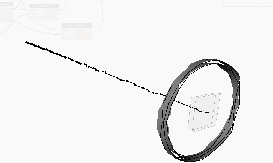
So far I have the circles created in the right spot (which I’d like to replace for an adaptive family in the future. Sort of a circular conceptual mass or wall if that’s possible) and I’d like now to create the surface all along the curve.
I only used the Y-Axis for my circles because that’s how my example was setup. If your tunnel is (generally) going in a cardinal direction you should be fine just picking an axis, but you could also get the vector of each line between points (or a line of best fit for the whole tunnel).
In your last image you seem to be missing the “center lines” for your guideCurve input, but besides that I think you’ve about got it.
Thanks for the link. It seems quite interesting though. Is it also covering tunnel creation processes through Dynamo? It seems to be only talking about AutoCAD Civil 3D, Revit, and InfraWorks 360
I did a similar thing a while ago using an adaptive family and a list of coordinates of the tunnel centre line.
It was for a tunnel that was around 12km long, consisting of segmental precast rings
Let me know if you still need it, I probably have a copy of the family and Dynamo graph somewhere.
Those are great news! I am now looking at how to work with adaptive families in order to place them along the tunnel so if you could share those with me it would be great.
Hello everybody.
I’m new on this chat.
I’m french, so sorry for my bad english.
Concerning the tunnel modelisation, our method is;
REVIT+ dynamo:
First step;
Each ring position is a CoordinateSystem.
The position of the ring number n is a function of the ring number n-1 and the two entry curve ( x,y for the first one, z for the second one)
Second step;
Place an adaptive family on each coordinate system.
This adaptive family is a 3 points simple surface, on wich we place a face base family, the ring.
I’m afraid I can’t share the complete solution as it was for a specific client/project.
However, refer this link for a sample Revit (2015) file- with just 200 rings- you can extract the adaptive family from there. For the Dynamo part, you basically feed in 2 points for each instance of the family (start and finish) The start point of one ring will be the finish of the one before it.
There a number of solutions in the public domain, using different approaches- some like mine use adaptive families, some use sweeps. You might need to take different approaches for the tunnel itself or things in the tunnel, like cable trays, lighting, track. Refer my post on cable trays below