Automated Scan-to-BIM Workflow – Parametrizing Dead Geometry?
Hello Community,
My name is Jeff, and I’m currently working on my bachelor’s thesis, where I’m trying to implement an automated scan-to-BIM workflow.
So far, I’ve managed to convert a point cloud into a highly simplified building mesh. The mesh consists only of simple, planar surfaces and contains no holes. These surfaces can be consistently classified as wall, slab, or roof.
Using Python and IfcOpenShell, I was able to create individual IFC building elements from these surfaces. The resulting IFC file can then be imported into Revit.
Problem:
Although the imported elements are visible in Revit, they are not editable.
For example, object snaps don’t work, which makes manual reconstruction difficult.
I thought I was almost finished — but it turns out that parameterizing the geometry is much more difficult than I originally expected.
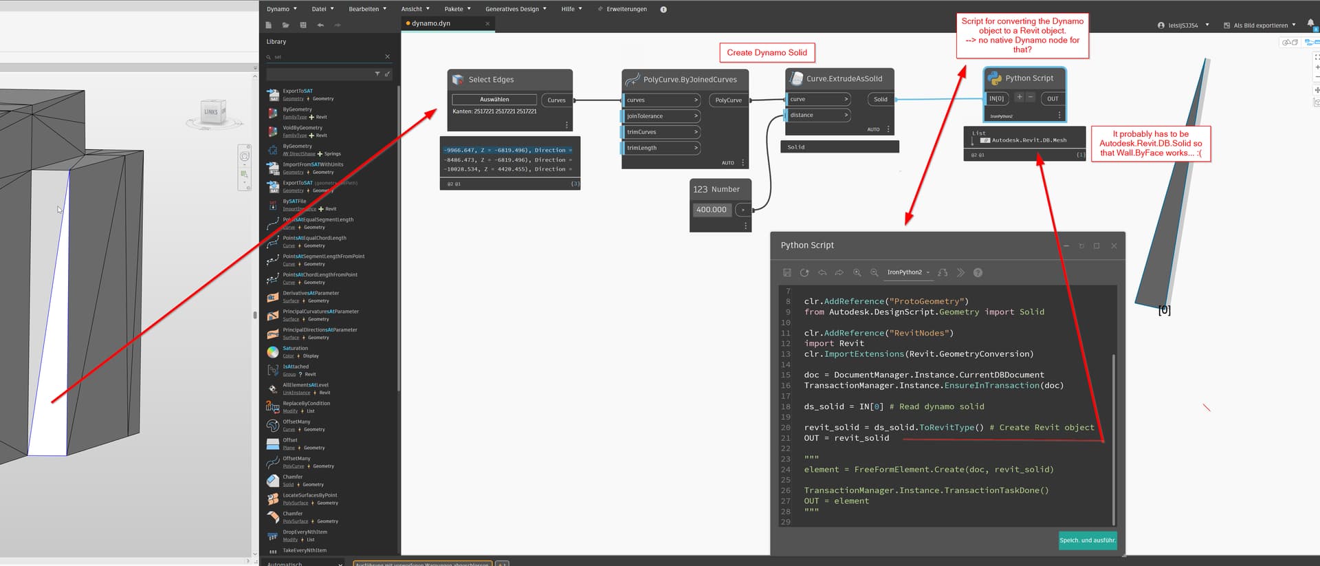
My initial approach was to extrude the individual surfaces directly in Dynamo.
However, from other forum threads, I’ve learned that Wall.ByFace requires mass surfaces.
I haven’t been able to figure out how to automatically reconstruct valid mass surfaces from the imported geometry (OBJ/IFC).
The required geometry should be there — right?
Do you see what I might be doing wrong? Or should I consider a completely different approach or software?
IFC File Download
Since I’m unable to upload the IFC file here, you can download it via this link:
for some reason, the file link doesn’t work. but i think you can isolate the bottom edge of the face and use one of these since they only want a curve.
Yeah, I think you want to be super clear about exactly what your final output will be…
I would mess around with the native Revit tools and see if you can make what you want to achieve, then try coding it.
The wall ‘by face’ is meant to be generated from a Revit mass, and they are always solids… And as noted, when you create it in Revit, Revit assigns ‘references’ to the geometry, allowing you to dimension it.
If the important aspect to you is that the point cloud to shows every 1mm variation in the wall, then you’ll likely not get full parametric capability, you’ll have to just make an element with a Wall classification.
If you want a proper native wall, it won’t have all that variation, but you could construct it just from a loop of lines around the wall edge, like the nodes above.
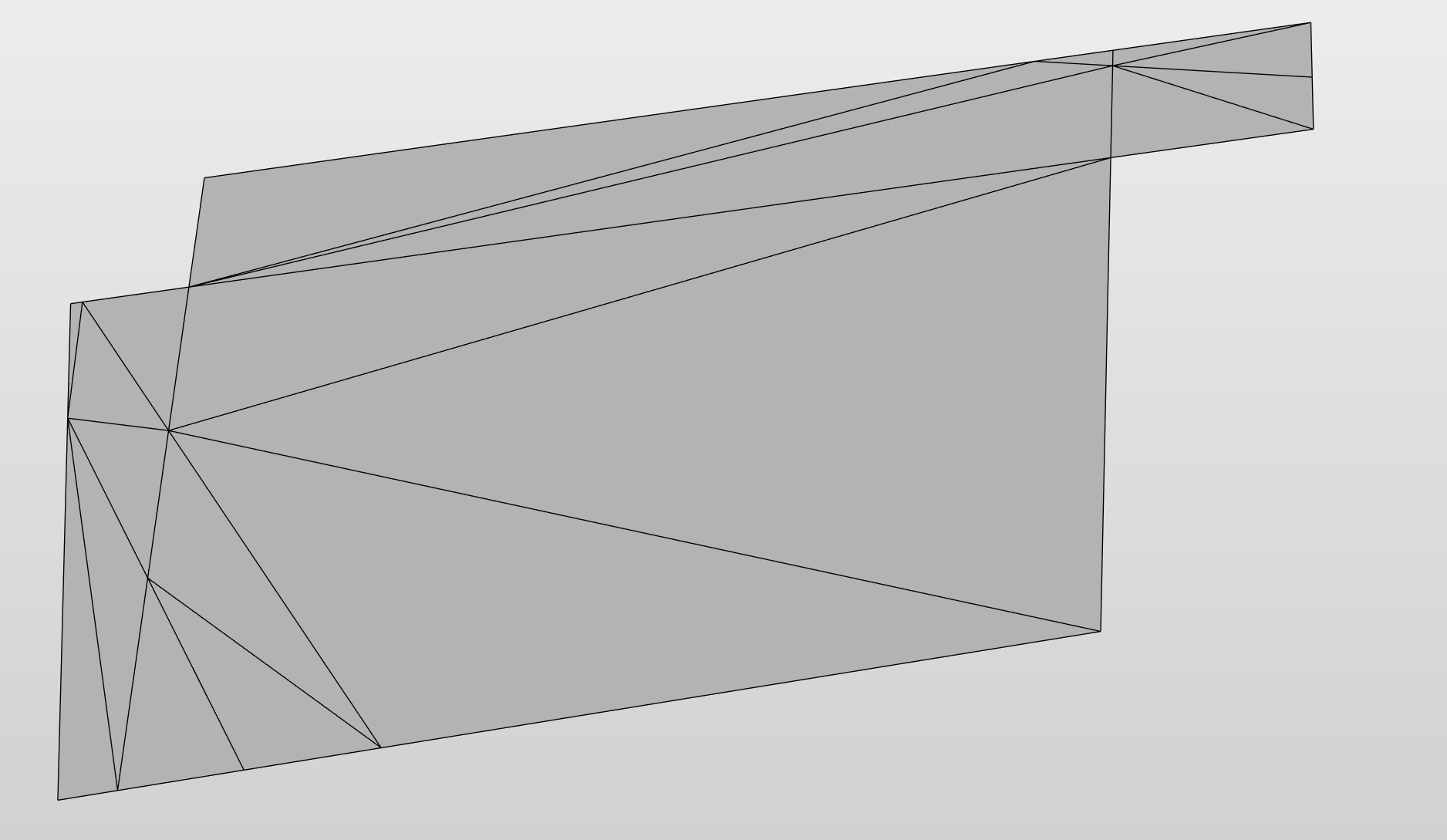
How complex is the mesh? This will matter a TON as if it is as simple as this appears to be it could be converted to a solid and that solid could be used to generate a mass, and that mass will allow wall/roof by face (one wall per triangle).
If you are getting much further from that in terms of detail then you will need to rethink the workflow - the initial mesh is insufficient for parametric object creation (not just Revit - every BIM tool I have seen fails at pr metric objects built from point cloud meshes). As @Mark.Ackerley mentioned shifting to a ‘how would I manually’ mindset might be a good first step.
Thanks a lot. I’ve added an alternative link for the file.
I also considered the curve-based approach, but since some faces are more complex than just rectangles, it might be a bit tricky to handle them using only a curve.
Hi Jacob,
the meshes consist of simple planar faces — each face could be represented solely by its outline. The triangulation comes from the Python package trimesh, which internally operates with triangular structures.
As the next step, I’ll try to generate solid geometry from these outlines. Should be doable — even as a Revit newbie!
Hey Mark,
for the final output, I’d like to generate a simplified model without details, but with proper wall elements. The models will be used for telecom site planning, where a generalized representation of the facades is sufficient.
However, for the building permit, the authorities also require windows to be included. These will be added manually later, but for that to work, the model needs to contain real wall elements that can accept window inserts.
I’m not sure if the native Revit tools are actually easier than coding, but I’ll give them a try
I think it’s important to keep the difference between the simplicity of the dataset you show and a real world dataset. The point clouds I have seen don’t triangulate this cleanly using any triangulation method. They’re usually far less complete in some areas (we don’t have the top side of the canopy or where the wall meets the canopy on that side of the building as we couldn’t get the scanner into a safe position to do so) and far more detailed in others (walls usually look more like a cliff side in the Grand Canyon than the 20 triangular faces you see here).
That said, with the number of faces you have here, you should be able to write a few lines of Python to convert the mesh to a polysurface, and then a single line will suffice to convert that to a solid which I think you can convert to a Revit solid via ToRevitType. If the mesh is simple enough it should convert to a solid. If not you can try exporting the solid to an SAT file and importing that as a new solid in a mass family environment which you can try to use to generate walls by face.
However walls by face behave differently than a regular wall. Keep this in mind as it will mean stuff like a window which wants to be placed in such a way as to have a seam or vertex between [2, 3, 4… 5000, 5001…n] different triangles won’t correctly sit across all of the faces and cut them correctly. And adjusting the location will be beyond difficult…
Hi Jacob,
Thanks for the detailed response. This is a real-world dataset that was generated through photogrammetry and originally contained 800k points. The geometric reconstruction was done using a tool from TU Delft (see here if you’re interested in that).
I tried your first approach, but unfortunately, Revit converts the Dynamo solid into a mesh object. And unfortunately, this already happens with really very simple geometry (just one triangle). I’ll try the SAT export method later this evening.
Try a simple cuboid with 12 triangles. Revit won’t accept any open faces in the mesh, and in fact the triangles have to have aligned edge directions in some cases.
I think that is the nub of it… If you need complexity, you probably won’t be using native tools…
I wonder if it is easiest to deal with everything in Dynamo and only pull dumb things… You could chop a hole from your solids in Dynamo, place the ‘wall’ and then place a ‘window’ (imported instance categorised to Window) into the hole? Neither native, but still giving you our output.
I think you only really need native if you are going to hand someone the Revit for them to work into with new doors, windows etc. Mostly when I get a survey, that’s what I want.
Though if it is instead for record files, maybe it’s not important.
When I manually select walls in Dynamo using Select Faces, they can be converted into walls via Wall.ByFace.
But as soon as I select the faces automatically, they suddenly get rejected again. Same object, same data type, different result. Problem can’t be the surface this time. Do you know a trick for that?
 Automated Scan-to-BIM Workflow – Parametrizing Dead Geometry?
 Problem: