Hi;
I am Alias user, i accidentally watched some topics on adaptive components on revit and dynamo interoperability.
I was hocked by the neatness of the process of making pattern based on 3 or 4 points generated from dynamo’s math, and then modeling freely based on those points as a unit.
I think it is a big loss for Alias users not to benefit from this technique which will be useful in generating complex patterns that modeled in Alias and distributed on points grid from dynamo.
For example, a grill of car, it would be super easy to model the unit of that grill and make it adaptive component, then apply to the points grid in dynamo.
I know that both revit and Alias are completely 2 different beasts, but a package with similar functionality would be a worthy addition to Alias, the new member to parametric universe.
Thanks and waiting for opinions and feasibility
you can think of an adaptive component as a function of n input points. You can make a custom node, python node, or c# node in dynamo which takes a list of input points and returns some geometry. Then you feed lists of lists of points to that function. This is one conceptually similar approach.
Seems practical, the only problem that i know nothing about programing languages, So i hope that Autodesk team, or an eager programmer would consider making that in the near future.
well the first option is to use a custom node, which only requires using dynamo nodes, and the custom node functionality which lets you embed a graph within a node. It’s tricky sometimes and not as reliable/easy to debug, as the other methods, but it would be a good starting point and is flexible.
Hi,
just came about the same question and think it would be great for interaction between alias and dynamo, if there was a similar feature like adaptive component. Did you get any further with python or custom nodes and would like to share?
Hi @andber ,
So something I’m currently looking at, together with a colleague, is multi surface patterning. The goal is to allow the user to give any numbers of input surfaces, and a distribution of grid points (2 dimensional), and then the script would take care of the placement of points and/or objects on your input surfaces.
Would this already help? If not, could you share a link, video or other supporting material on what you are looking for to achieve? I am not familiar with Revit.
Thanks,
GG
Hi Michael,
thanks for the reply.
I am not familiar with revit as well and would like to stick to an alias/dynamo workflow.
What i am trying to achieve is something like this:
left my 2 surface alias panel, right my target: to mapping the panel on a wavy surface (grid via lunchbox, diagrid e.g.)

I know it is possible to extract points from the alias geometry, map those points to a grid and build new surfaces again. But for quick variants and explicit control of my panel inner design I rather stick to imported alias surface geometry and stretch/morph this to a new grid pattern. I think this is the whole great deal about revits adaptive components and families.
I spent a lot of time searching the forum posts, nearly all rely on revit or packages that need revit installation. I found these quite inspiring:
https://forum.dynamobim.com/t/mapping-dynamo-built-panel-to-lunchbox-surface/8120
https://forum.dynamobim.com/t/stretch-morph-dynamo-solids-to-fit-a-new-shape/22909
Alias curves stretch morph accordingly to this sample. Now I need this for a surface/solid.
Any idea is very much appreciated, and would be awesome for alias users!
Thanks
Hi @andber,
Could you simply share your Alias surfaces on the left, and the surfaces you want them map onto (e.g. in the shape of the right)? Then I could use my current version of my multi-surface patterning script, to see if it would solve your issue.
Can’t share my script yet, but I hope to be able to do so soon.
Thanks,
GG
Hi Michael-GG,
just saw your reply, thanks for looking into it. Please find attached a .wire file with both parts and two separate .sat files with source geometry and aimed surface to map on. Interested to see what your script is doint to it.
Thanks,
Andreas200304_abd_spring_form_by Geometry_1.1.wire (104.1 KB) 200304_abd_spring_form_by Geometry_aim_1.1.sat (11.2 KB) 200304_abd_spring_form_by Geometry_source_1.1.sat (33.2 KB)
Do check this video from AU
Pattern developed based on this video
Instead of image sampling i have used a sequence input. We need pattern toolkit package installed inorder to get the pattern nodes

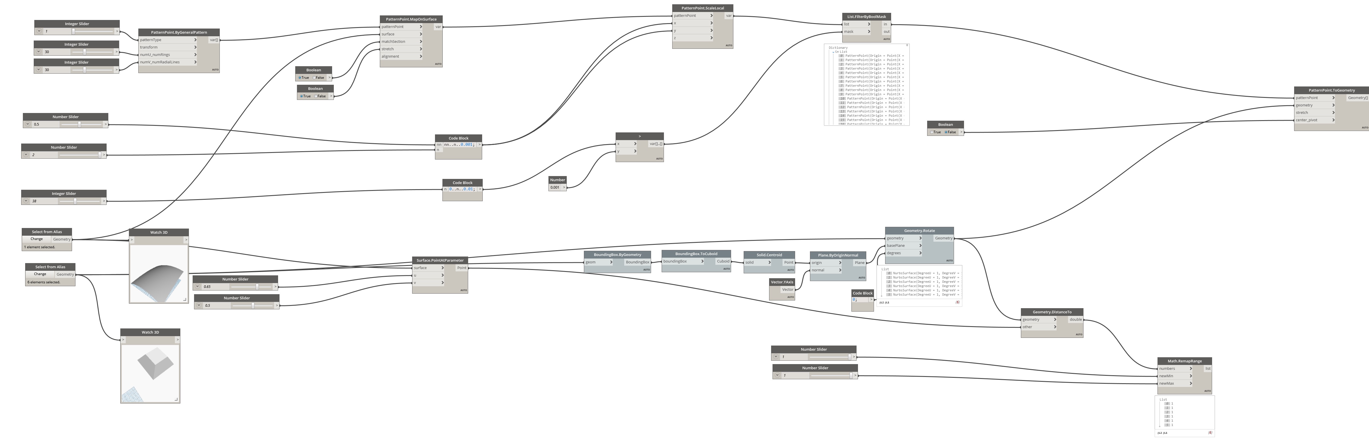

If the stretch booleon is switched to false all cells will be stretched to a common cell edge.
Regards
Hi Andreas,
Is the post from d.b. above enough for you?
If that’s not the case, I looked at your sample file. For that one, I don’t even think you would need my approach. How I would do it:
The pattern you want to place is rather simple. So I would build that pattern in Dynamo itself, based on one single center point (CP) on your target surface.
From this center point, calculate the four corner points. From these 4 points, create a base surface, and modify the base surface by moving the CVs into normal direction, which you get from your target surface, to get your wanted shape.

Once you have this description on how to create your pattern shape, you can then simply create a grid of UV points on your target surface, and then use the notes to create your pattern at those points.
Please let me know in case you need more explanation or guidance.
Cheers,
GG