Hello everybody
I am looking for a way to create geometry patterns using images. Afterwards I want to export the contour as dxf and laser cut it. The result should look something like this: Raiffeisen Zürich
I’ve only seen tutorials that create circle patterns.
Is the desired conversion with dynamo possible?
Best regards
Raphael
Look into the pattern toolkit. Info can be found in the Dynamo for Alias tutorials, starting with this page and continuing to step 9 (which has more of what you’re after):
https://knowledge.autodesk.com/support/alias-products/learn-explore/caas/CloudHelp/cloudhelp/2019/ENU/Alias-Modeling/files/GUID-AD0EF4F8-EE11-4397-B6F0-FD558E80DC05-htm.html
Thanks for the link to the tutorial. This goes exactly in the direction I am looking for. It even shows a similar pattern as in the photos.
Does Dynamo’s performance depend on the software used? I have seen that a Dynamo connection is offered for Fusion 360. Can these features be used with Fusion 360?
Yes and no. Dynamo’s performance will be consistent for most applications, but applications take different amounts of resources to run, and they have varying degrees of stability with the content produced - ie what works well in Alias may not work well in Revit due to scaling and such. The most stable and fastest is likely sandbox as a result, but the Formit and Alias integrations are also very light.
Most of the fusion 360 connection is for setting parameter values - the geometry bits have to be imported and exported directly by the respective programs. I have also not seen a direct Dynamo 2.x integration with fusion for parameter manipulation yet.
I worked through the tutorial and took some pictures for testing purposes. How can I export the obtained polylines as dxf? The node “PatternPoint.ToPolygon” shows an error, because it probably cannot draw all polygons. How can I handle this?
And how can I hide polygons that are smaller than a value?
Sorry for the many questions, I’m working with Dynamo for the first time today  Test.dyn (39.8 KB)
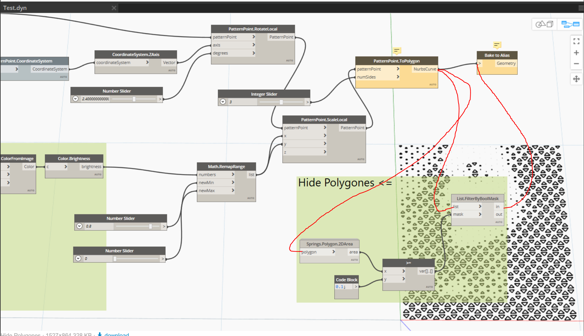
@OibelTroibel I cannot answer your question about the dxf but to hide small polygons you can do the following.
Springs package has a node called Springs.Polygon.2DArea. Use this to get the area of each polygon.
in = all polygons with an area greater than or equal to 10 (my defined minimum input).
out = all polygons with an area smaller than 10.

Why not just write them to the application directly? What is your end platform?
@Steven I can’t find a package called Springs. Or where do I find the package? I found a package called spring node from dimitar.ven, but I get a message that this package already exists.
@jacob.small I want to be able to process the contours with AutoCAD or Inventor and then laser the product out of a piece of sheet metal. I can’t get along with Alias yet, because it behaves completely different than all Autodesk products I know so far.
Civil 3D 2020 would work then for a direct path to DEG then, or FormIt works with an export to DXF.
Spring Nodes is the package which Steven is referring to.
@StevenThanks for your tip. Unfortunately, I’m not sure where to link the node group. I always get an error message that the list must not be empty.
What must the connection look like?
I have attached my current Dynamo project.
Test.dyn (46.7 KB)
Hi,
Are you able to post screen captures? I do not have your Revit file to test anything.
For a Revit/Dynamo option: take a look at the Dynamo primer on zero touch nodes
There is an example that is more or less what you want to do:
https://primer.dynamobim.org/11_Packages/11-5_Zero-Touch.html
Andrew
Edit: Updated code to create polygons instead of solids
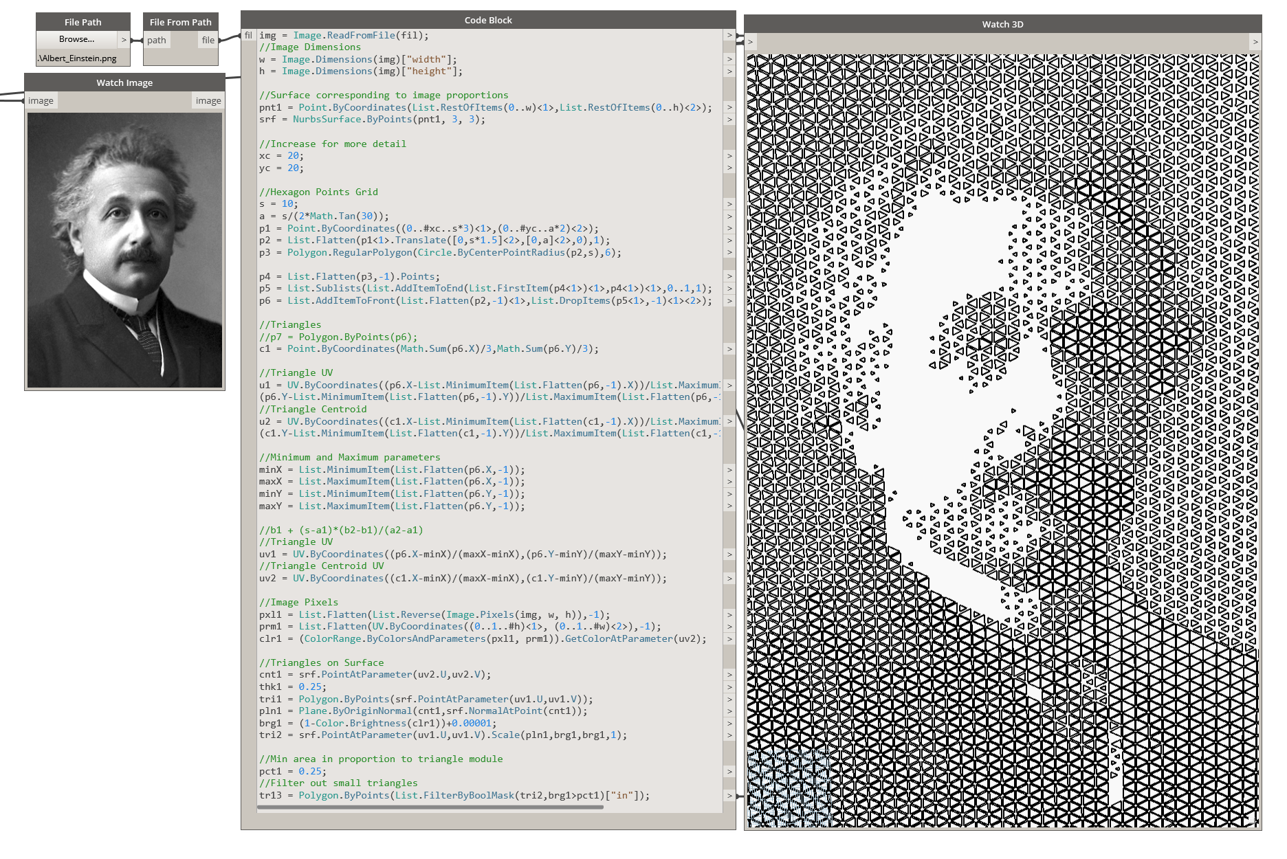
img = Image.ReadFromFile(fil);

//Image Dimensions
w = Image.Dimensions(img)["width"];
h = Image.Dimensions(img)["height"];

//Surface corresponding to image proportions
pnt1 = Point.ByCoordinates(List.RestOfItems(0..w)<1>,List.RestOfItems(0..h)<2>);
srf = NurbsSurface.ByPoints(pnt1, 3, 3);

//Increase for more detail
xc = 20;
yc = 20;

//Hexagon Points Grid
s = 10;
a = s/(2*Math.Tan(30));
p1 = Point.ByCoordinates((0..#xc..s*3)<1>,(0..#yc..a*2)<2>);
p2 = List.Flatten(p1<1>.Translate([0,s*1.5]<2>,[0,a]<2>,0),1);
p3 = Polygon.RegularPolygon(Circle.ByCenterPointRadius(p2,s),6);

p4 = List.Flatten(p3,-1).Points;
p5 = List.Sublists(List.AddItemToEnd(List.FirstItem(p4<1>)<1>,p4<1>)<1>,0..1,1);
p6 = List.AddItemToFront(List.Flatten(p2,-1)<1>,List.DropItems(p5<1>,-1)<1><2>);

//Triangles
//p7 = Polygon.ByPoints(p6);
c1 = Point.ByCoordinates(Math.Sum(p6.X)/3,Math.Sum(p6.Y)/3);

//Triangle UV
u1 = UV.ByCoordinates((p6.X-List.MinimumItem(List.Flatten(p6,-1).X))/List.MaximumItem(List.Flatten(p6,-1).X),
(p6.Y-List.MinimumItem(List.Flatten(p6,-1).Y))/List.MaximumItem(List.Flatten(p6,-1).Y));
//Triangle Centroid
u2 = UV.ByCoordinates((c1.X-List.MinimumItem(List.Flatten(c1,-1).X))/List.MaximumItem(List.Flatten(c1,-1).X),
(c1.Y-List.MinimumItem(List.Flatten(c1,-1).Y))/List.MaximumItem(List.Flatten(c1,-1).Y));

//Minimum and Maximum parameters
minX = List.MinimumItem(List.Flatten(p6.X,-1));
maxX = List.MaximumItem(List.Flatten(p6.X,-1));
minY = List.MinimumItem(List.Flatten(p6.Y,-1));
maxY = List.MaximumItem(List.Flatten(p6.Y,-1));

//b1 + (s-a1)*(b2-b1)/(a2-a1)
//Triangle UV
uv1 = UV.ByCoordinates((p6.X-minX)/(maxX-minX),(p6.Y-minY)/(maxY-minY));
//Triangle Centroid UV
uv2 = UV.ByCoordinates((c1.X-minX)/(maxX-minX),(c1.Y-minY)/(maxY-minY));

//Image Pixels
pxl1 = List.Flatten(List.Reverse(Image.Pixels(img, w, h)),-1);
prm1 = List.Flatten(UV.ByCoordinates((0..1..#h)<1>, (0..1..#w)<2>),-1);
clr1 = (ColorRange.ByColorsAndParameters(pxl1, prm1)).GetColorAtParameter(uv2);

//Triangles on Surface
cnt1 = srf.PointAtParameter(uv2.U,uv2.V);
thk1 = 0.25;
tri1 = Polygon.ByPoints(srf.PointAtParameter(uv1.U,uv1.V));
pln1 = Plane.ByOriginNormal(cnt1,srf.NormalAtPoint(cnt1));
brg1 = (1-Color.Brightness(clr1))+0.00001;
tri2 = srf.PointAtParameter(uv1.U,uv1.V).Scale(pln1,brg1,brg1,1);

//Min area in proportion to triangle module
pct1 = 0.25;
//Filter out small triangles
tr13 = Polygon.ByPoints(List.FilterByBoolMask(tri2,brg1>pct1)["in"]);
Sorry for my late reply, I have been very busy the last few days.
@Steven I made a screenshot of my project and don’t know where to connect the hide polygons part. Can you help me there?

@Andrew_Hannell Thank you very much for the link. I have to take a closer look at it.
@Vikram_Subbaiah This looks very exciting, but is even less understandable for me at the moment. How would you export the outlines as .dxf?
Translated with www.DeepL.com/Translator (free version)
Hey,
Export to dxf should be like this?
https://dynamobim.org/dxf-import-and-export/
Hope that helps,
Mark
@OibelTroibel are the polygons coming from PatternPoint.ToPolygon? If so connect the wires as shown below.
Sadly this is for Dynamo Studio, which cannot leverage Dynamo 2.x content as it’s capped at 1.3.4 (and therefore no pattern toolkit so you’d have to build the tessellation of shapes on your own). ![]()
You can however look into the other ideas (Civil 3D, bake to FormIt), or even use LinkDWG package for direct creation of objects, all are viable solutions in 2.X.
Thanks Jacob,
Yes LinkDwg has a working node ‘ActiveX.ExportGeometry’…
But there are a couple of issues, I’m sure they could all be solved with a bit of Python, it’s an editable node 
I don’t think the node can deal with solids or surfaces, so I made polygons.
I don’t believe the node can deal with multiple layers. Maybe someone else can get it working, I tried various list structures.
You’ll need to reduce the number of colours to something more manageable? unless you want 1200 layers…
Here’s my attempt, excuse it’s ugliness! I didn’t bother doing an export for every colour. You can see my basic way of rationalising colours… I’d probably do it in Photoshop instead!
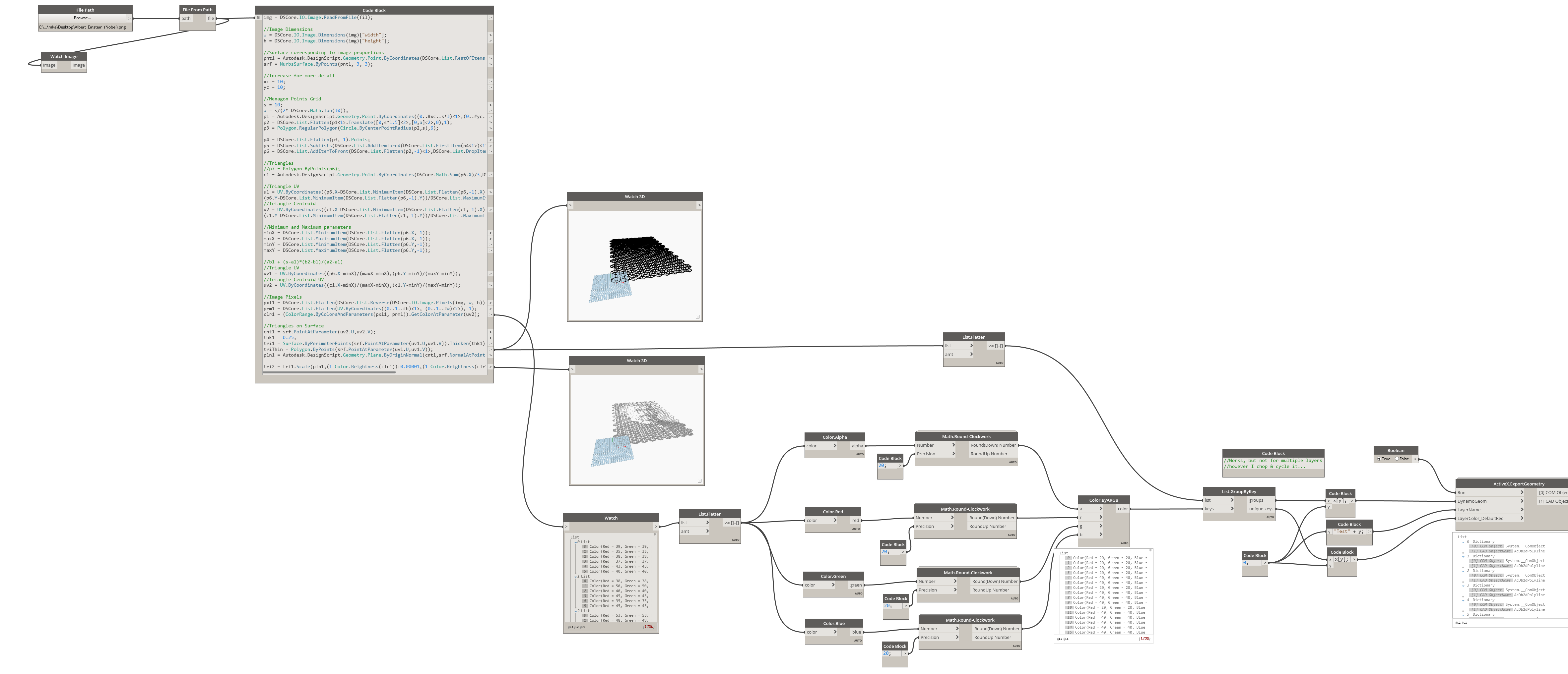

Hopefully that’s of interest,
Mark
Below are outlined two possibilities. There may be more.
Please note this response builds on my earlier post (that was edited to support this)
imageHex.dyn (20.5 KB)
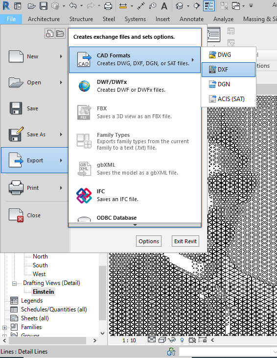
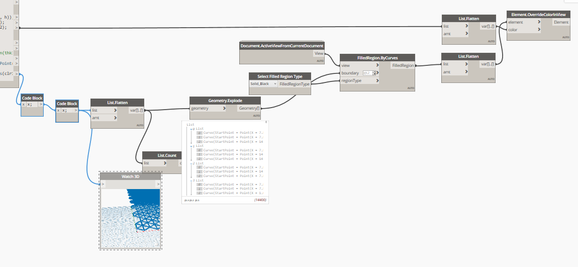
Option 1: Dynamo Geometry > Revit Drafting View > Export to DXF

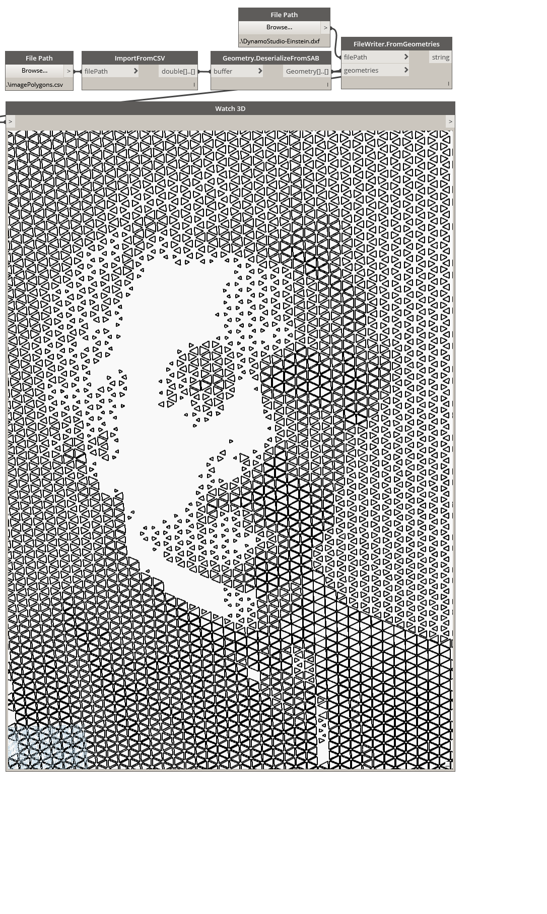
Option 2: Dynamo (ver 2.x) Serialize As SAB > Dynamo Studio DeserializeAsSAB > Export to DXF
Dynamo (ver 2.x) …

Dynamo Studio 2017 …
imageHex-Studio.dyn (5.0 KB)
