I’m building a context model by extruding closed polylines from a DWG files. Then using custom nodes to place either a gable or mansard shaped roof mass on the top of each surface of each mass solid. However, I’m having some issues with the gable custom node. The node takes in the top surface of a mass, translates that surface to a given height, scaling it inwards to get the slanted sides and finally lofting both bottom and top perimeters curves from the surfaces. This only works when the base surface is orthogonal to the world coordinate system. If the base surface is rotated, the shape of the mansard roof stays orthogonal resulting in a twisted shape. How can I fix this?


I tried to solve this problem by adding these nodes to rotate the coordinate system according to the underlying mass.

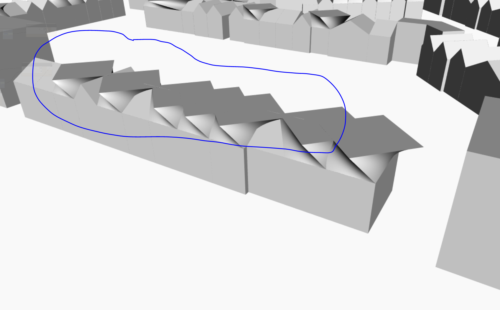
But got an unexpected result
