Getting an odd error sometimes with Curve.Patch saying WIRE_SELF_INTERSECTS2 - wire has self-intersection. Which it can’t as my Polycurve is made from joined tangent arcs with no overlap and it only happens on some variations of the shape and the form and is always a closed curve. Is there another way to find an area of a closed curve?
This seems to be a problem/bug that has come up in the past but none of the answers I have found seem to solve it. I can’t post the file as its part of a live project. Working in Dynamo Sandbox. (Dynamo Core 2.1.0.7500. Could not get the later daily builds to run as they could not find the geometry library dll.
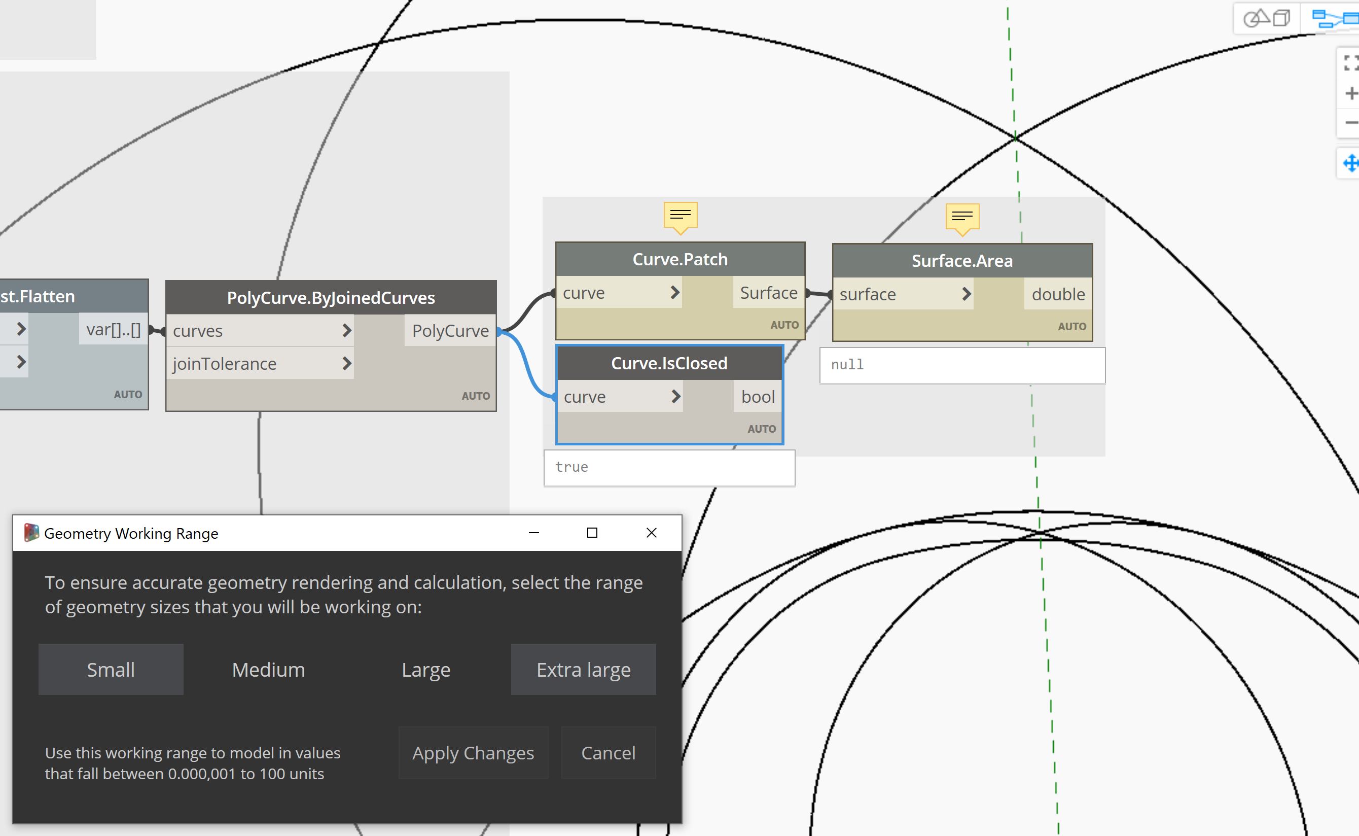
First up, confirm this isn’t a geometry working range issue by checking what happens if you change the setting higher or lower. After that things get more involved. What follows is more or less how I would ID the problem location - even if we think the geometry doesn’t self Intersect we need to confirm it doesn’t as Dynamo says it does, sooooo…
Is this a polycurve or a series of lines? If it’s a polycurve the this usually means the item ‘backs over’ itself or has a line which crosses over a previously drawn line.
Use a Geometry.Explode node to get the source curves, then use a Geometry.Intersect with cross product lacing to confirm you only have points resulting using an Object.Type and a group by key node. If you have a line, you can quickly ID where it is and why.
If you only have points, count the number of items in each sublist after the cross product intersection node - each curve should only touch another curve at it’s endpoints, so each sublist should be 2 items long - if you have 3 or 1 or any other number look at those closely.
If that doesn’t work, so a save as of the file, slap a Remember node into the graph (from Refinery) to remember the data two nodes before the problem node, run the graph to commit the geometry to the dyn, and then delete the upstream nodes to the left of the Remember node and everything right of the problem node, and upload that file to the forum.
1 Like
Ok, I think I found the error for this code at least. I had forgotten to include adding some error checking for my arcs. Still having issues with “If” Filter but will start a new post for that as its off-topic.
Regarding Geometry Working, I had this set to small but Medium would be the tolerance I need but as you can see this makes the circles faceted. Render setting is set to high.
Working Code, Faceted Circles, Sometimes are a few switches between small medium and turning a few components on and off this resolves itself for that session but returns next time the file is open.
Broken Code, perfect Circles
Is there any way to have circles displayed correctly without changing the working range/tolerance to small as I don’t need this level of tolerance just the circles not faceted. The circles around the origin currently I am not working miles from 0,0,0.
Working on installing the Refinery package just need to install Revit. Shame Refinery needs Revit and can’t just work with FormIt etc. Also would need to check with the client if I can upload anything from the project, but that’s a different matter.
My guess is that you are drawing really small circles (I guess it at 0.06125 units based on the degree of segmentation you’re seeing), but really far from the origin.
All geometry engines have a working range, and when you go over or under them you get bad results like this. Try drawing the solar system in your favorite application - start with the sun using real world units, then try and draw Mercury, Venus, Earth… I’ve found that most fail at Mercury.
There is usually a way around this (say using just data instead of geometry), and typically this type of scaling issue is a non-issue after the segmentation. That said, since we don’t have your graph we can’t really see how to be help you solve this problem.
Smallest Circle is around 0.06 units radius and largest is only around 15.00 units radius in this case meters (I know dynamo is unitless). So not a crazy number range which is why its odd that it fails to create proper circles visually. Especially considering the units are well inside the tolerance noted for medium on the geometry scale.
Also everything is based around (0,0,0) or close to it. I know the issues of working too far from the origin and also the computational issues of floating points calculations etc that give back bad geometry previews if your to far from the origin. Note this is only the preview from Dynamo Sandbox i am not linking it to any other software package currently.
I try to just use maths/data rather than geometry where possible when i am coding as its usually less computationally heavy thought for this project it was just easier this way that pure maths and the main issue seems to be main a visual one.
Regarding graphs is it possible to send it to someone offline rather than post it to the forum?
I think this is the other aspect to keep in mind here - the circles are still real circles, you’re just seeing a preview which has become segmented due to the scaling.
Feel free to PM me and if it’s simple enough or obvious enough I can give your graph a quick once over, but I’ve got more on my plate then I can handle if it’s more in depth. Also include your work email and I’ll see if I can find another resource based on resources through your professional affiliations, but no promises there either. You could also try and submit a case directly to Autodesk support as you would with any other product.
-jacob
