Hi there,
At the moment i am working on a Dynamo script that would allow to bring Civil 3D alignment points into Revit and then attach a adaptive profile to these points to create geometry (bridge superstructure). The points from Civil 3D are the right and left edges and axis of asphalt, exported from Civil 3D using Transportation Extension. After making some correction make the coordinates smaller, the result can be seen in excel file .
Points.xlsx (69.3 KB)
This road allignment is ment to be the most extreme case, as it has a transversal slope to both sides of the axis and in parts that changes to one side. Also the layout widens on one side.
After that I create the profile with 3 adaptive points, that would attach to the points from Civil 3D.
Family1.rfa (768 KB)
Next is the creation of the script in Dyanmo that reads the excel and places points and attaches the profile to these points.
Alignment no Civil 3D.dyn (714.5 KB)
For some reason, parts of these profiles are placed correctly (vertical), but after a certain point these profiles start to twist and tur for no apparent reason:
-as can be seen in the picture below, the profile becomes thicker creating sort of a jump.

-also one side of the profile starts to twist (one side of it is not completely vertical)
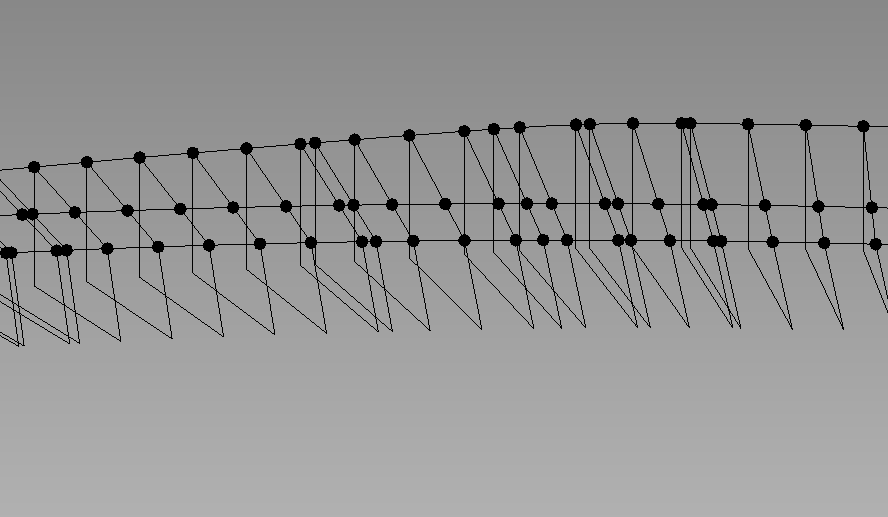
From Points2.rfa (1.1 MB)
Ultimately what i would like is for the profile to be placed completely vertically, without any twists and turns so that the geometry can be created correctly.
Maybe someone here can clarify what is the issue, as I have ran out of ideas what to do. Maybe there is another way to achieve this?