The idea is
Get a line from Floor plan view
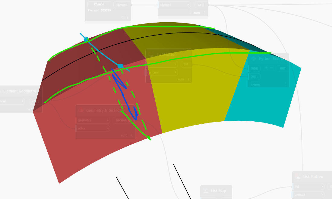
Extrude the Line intersecting with the Solid’s Top face = Comes back with a line on the surface
Use the line on the surface, and point at the intersection between Blue and Red line (Refer first post), and do a Plane that is Perpendicular to the Surface
It’s definitely something missing or wrong on how my Curve is working, or in your case, the edge
Thanks for the help!
also, never knew we can easily see hwo the geometry will be
I always had to run the script, delete the create family after doing so, just to see how the solid will end up like.
This Geometry.DifferentiateDisplay is really godsend.
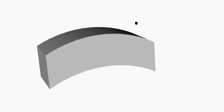
From top view, the cut is now perpendicular to the line
But in actual, i want it to follow the Planview line (Blue); where its slightly skewed
I probably shouldve showed it at a more skewed angle for easier understanding
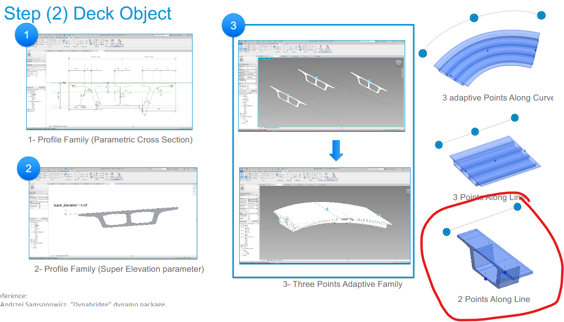
However, I would recommend using a two-point adaptive family instead of cutting the solid directly. This method offers greater flexibility and accuracy, especially for complex bridge alignments.
Here’s how it works:
The two-point adaptive family is driven by two reference points:
Point A represents the bridge cross-section (typically the bulkhead), and should be oriented perpendicular (90 degrees) to the segment’s centerline.
Point B should be aligned perpendicular to the bridge alignment, ensuring correct positioning along curves and transitions.
Additionally, it’s important to rotate the cross-section so that it remains perpendicular to the vertical profile — this ensures accurate placement and fabrication-ready geometry.
This method aligns well with the short match technique and can be integrated easily into a parametric or automated BIM workflow using Revit and Dynamo.
I also have a presentation where I demonstrate how to:
Model segmental bridges in Autodesk software.
Extract construction-ready data for on-site fabrication of segments.
Automatically generate 2D drawings from the 3D model, suitable for production and documentation.
At times, I encounter where Point A and B are in reverse.
Not all short match face is to the the same side in a span, say LHS ( At XY Plan rotation)
Would it still be possible for a script as such?
A lot to digest here
I’ve actually read just a little of these before, and was at lost when it comes to Rotation
I’ll slowly go through all these shared information again.
The angled line will cast an ellipsoid arc across the curve, this will generate two curve normals (at the end points) that are not on the same plane. The two normals at each end will create a hyperbolic paraboloid.
If your element has an alignment then use that to generate the cutting plane (say the point at the centre of the arc) which will approximate the cut.