I’ve been asked to create a model based on dwg’s which has curved surfaces on all 4x sides and glazing top to bottom. I’ve spend the morning looking into how I can achieve this using the Conceptual Design Environment. The more I do the more I think I am better of doing this using Dynamo.
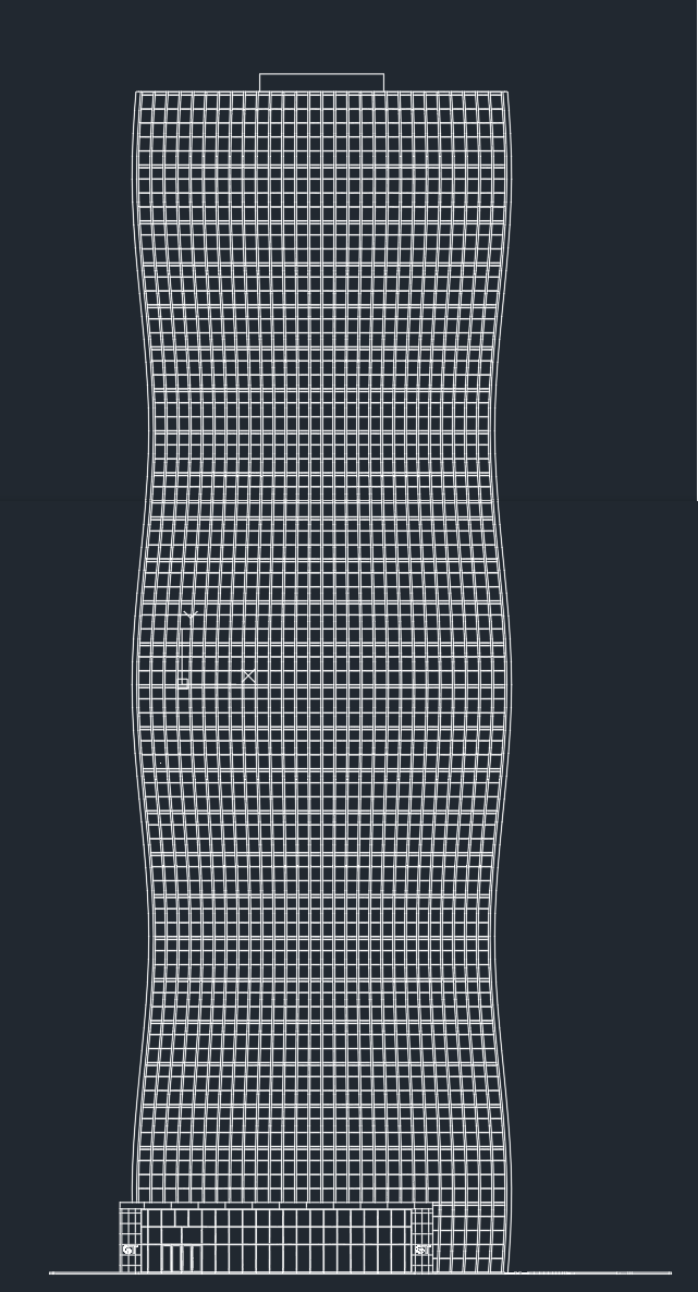
Below is a screenshot of one of the facades, the other 4 are for the most part identical (the entrance is different on two facades).
Having used Dynamo for many other things, I have never used it for modelling. What are some good resources to begin with massing before I go down this road?
I have more detailed drawings levels and panel breakup I will try to mimic before making it into a curtain wall facade (I’m certain this can be done?).
—edit—
Some thoughts on how I might do this
create rectangular tower
divide up the mass for levels
define start, intermediate and end control points (to get curve)
Thank you @solamour thats really great, I can definitely get started with that.
I have some questions
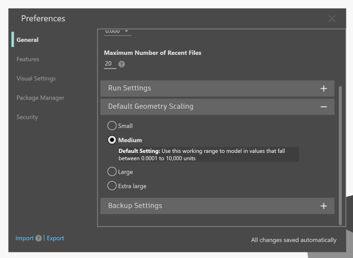
What are the input units? Maybe this is a Dynamo/Revit setting, the preview in Revit is very small, when I use mm’s I get a warning: Your inputs lie outside of the allowable modeling range
The z translation for Geometry.Translate - should this be an input for each level?
I’ve attached my progress. I know my min/max width for the curve and their associated levels, I’ve worked this into the script at the min/max curve. For the points on intermediate levels, how would I go about figuring these out? Do I manually create the PolyCurve.fillet for each or can this be worked out somehow?
I did this in base Dynamo, so unitless if you will In that case, you’ll need to appropriate them to a real Revit scale.
So my width was simply 75 units of … units If you are looking for a tower that has a set size, you’ll need to change all the dimensions in this graph to reach it.
Width goes from 75 units to 75,000mm if your tower is a 75m square.
Fillet goes from 10 units to 10,000mm if your fillet radius is 10m.
etc.
Dynamo is unitless, so you as the user have to define what units you work in. To push back into any given Revit project you should work in the units you are working with there.
Yes this is in essence the distance between the curves I’m using to sweep. This could be a singular floor, but in your image appears to be around 15 floors or so. So if your floor height is 3000mm that would be 3000 x 15 floors = 45000 z translation per level.
Understood on the units, in Dynamo I just use the same units I otherwise would in Revit. I can ignore the warning about limits then as well?
There are some 27 floors, I only make the curves for 4x (widest and narrowest points on specific level), I will probably do this for each level (it repeats). In your script you had a fillet in the corners, I tried changing this to a chamfer and now the division only occurs along one line (or face of the building) instead along the circumference.
I have found some Youtube videos to follow along but for now I want to try and translate your script to a Revit model to workout that workflow before going back to making a graph to follow the design intent.
This is because in my scenario the entire surface is a singular one, and in your one it appears that you have split ones. Try putting a PolySurface.ByJoinedSurfaces node afterwards.
Once again thank you for your input. This didn’t work but I’ll find a way to get it to work, I’ve found several tutorials to get me going down this path.
One thing I can’t figure out is how do I get the mass from Dynamo into Revit as a curtain wall? My colleague has made some progress modelling it which what I would like to generate from Dynamo
A lot of the tutorials seem to use adaptive components, I haven’t been able to find anything which takes my Dynamo generated mass and translates it to a curtainwall such as the above.
CurtainSystem.ByFace (Clockwork)? But you can’t have curved mullions…
Maybe look in the Synthesize Toolkit Package?
I would use divided surfaces however. Adaptives are fun!.
@Marcel_Rijsmus adaptive families are one I haven’t played with (much if at all). Instead of a CW (system) you would make all the panels using an adaptive family (which is what the earlier script shared by Sol does)? Are the horizontal/vertical mullions created as part of the family, or how would you achieve this outside of the same adaptive panel family?
Because of time constraints I’ve had to do all of this without Dynamo, the mass was easy, the curtain system was also fine but working on the minor difference (adding grid lines, changing out panel types) was time consuming, fortunately I was able to mirror two sides. The above snip uses CW system in elevation the vertical mullions are curved sideways but faceted between levels. Not ideal but we’re able to convey out intent.
I did however make a script to edit CW grids (removing segment) so still an element of Dynamo in this task.
@solamour that worked, I tested it but as above I ended up doing it all manually.
I do want to try and make this again using Dynamo, I think the overal shape will be the hardest to achieve and will come back on this if I need some help of the forums!