First time using Dynamo, wanted to understand if this type of geometry can be created by selecting lines or polylines in AutoCAD, before I get started. it should also be dynamic.
Thank you
John
First time using Dynamo, wanted to understand if this type of geometry can be created by selecting lines or polylines in AutoCAD, before I get started. it should also be dynamic.
Thank you
John
Certainly doable - will be much easier with the Dynamo for Civil3D integration. Does the initial (red) curve exist already?
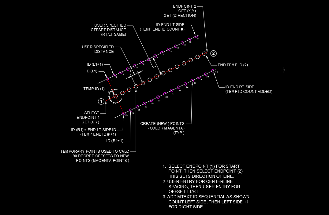
Like this?

Guys, mzjensen,
yes just like that! does the code select an original line or does the user pick the endpoints for 1 and 2, then it draws that line, and that line is now is dynamic, and controls the prorated spacing of the offset objects.
Q: in Dynamo, what happens when you save the file and you reopen the dwg, do the objects controlled by the code sample, circles in this case ( blocks as I figure how to use this) still stay connected in some way or do you run the code sample again? if you have to rerun code or move the controlling object, what happens to the original objects, are they now static? if the code is rerun, do the old objects need to be deleted. meaning the code is not like an offset civil 3d alignment where you move the centerline object and the connected objects move with it.
Q: can one code graph be use to run another code graph? lets say I have this one do it’s magic, can another code graph be run which gets or uses the original line in it’s new position and run some other code block based on that new location.
Q: I’m guess this same type of code could be used with a polyline, with curves? or would that need additional import. lets say I’m setting utility poles along a roadway centerline and what to set the poles every 100 feet along a centerline, with some offset value. but the start location to start inserting blocks is different then the start location the alignment or controlling object, like civil alignment or polyline, and I need to place poles on one side, I’m guessing you can prompt the user to select a side and a start location. I ask only because I haven’t seen any samples yet that prompt the user.
This type of code interaction looks very promising.
Ok, how do I get started? I guess it’s all about trying samples. when someone posts a graph, and you see a sections that might work for you, is there a way to copy that code? or is it just used to show design flow.
Thank you, this is good stuff.
John
btw how do you make the movable images like the one attached?
Jacob,
No. the idea was to have user pick start and end locations on screen, much like placing a line in AutoCAD, after objects are placed or inserted into the dwg the user can move start or end point to update graphics, circles or blocks.
lets say we use the example below, we are placing utility poles and the spacing variable must have a plus/minus to take into account of terrain or other conditions. user could run different spacing to come up with the best placement solution for there project. I have no idea about utility pole placement, just guessing that’s how it might work.
The goal would be to use an civil 3D alignment, but if the concept is easier to use polylines to flush out the code sample I can use that until I learn how to use the civil objects.
Thank you,
John .
I really appreciate your enthusiasm! Welcome to the community by the way. ![]()
You need to rerun the graph to get new results. If the previously created ones are changed depends on if element bindings were created, which is a more advanced topic.
Not really, but you could convert your graphs to a custom node and have the results of one custom node inform or trigger the next. There are also ways to have Civil 3D run graphs in sequence via the command line.
For the most part - with any attempt to write code there will be some ‘gotcha’ moments.
I recommend most people start here if you have Revit access (get a free trial if not): https://primer.dynamobim.org/
Skip nothing. Do all exercises even if you don’t think you will need the result. It is about the methods, not the outcomes. There are also AU sessions from 2019 and other resources out there for C3D stuff, but I am a Revit guy at heart. A ‘integration agnostic’ version of the primer has been on my personal wishlist for awhile now, but such an effort is quite time consuming.
I use this: https://www.screentogif.com/
I think it is easier to have Dynamo pick the points rather than the user, or have the user place blocks rather than just click in space at the moment - not sure if there is a ‘pick points on surface’ user interface at the moment. Having the user select an alignment works quite well.
You just described using generative design, which is one of the most advanced uses of Dynamo at the moment. You can find out more about it by checking out some of the recent AU sessions - ie: I have an example of using it to find the optimal location of a quidditch stadium in my class Generative Design at Hogwarts: Using Tech Instead of Magic. Like any advanced topic, best to learn basic Dynamo stuff first rather than jumping into the deep end right away.
Jacob,
I’ll see what kind of trouble I can get into today playing around with some samples after viewing the primer stuff.
Thanks
John
@jcoon here are the files for the quick example I posted earlier.
Offsets.dwg (601.3 KB)
Offsets.dyn (109.1 KB)
It just uses a line that is already in model space. I 100% agree with Jacob’s perspective - it will probably be easier to do it this way or something similar such as having the user select and move blocks, circles etc. But if you are really wanting to select the points, then you’ll have to tap into the AutoCAD API using a Python script (example here). Note that if you ever decide to run the script with Dynamo Player, then you won’t be able to set this as an input (hence the recommendation to use some type of already-created geometry in model space).
I put together an example of this for you to try out as you start working with Civil 3D objects. Hope it helps!
PoleExample.dwg (3.3 MB)
PoleExample.dyn (81.6 KB)

mzjensen,
This is a fantastic sample, just what I was looking for, a really good real world example.
let me look at the work flow to see if I can figure out how you did this. I’ll get back to you with questions I’m sure after I take a look…
Thank you,
John
MZjensen,
A lot of this looks similar to the old VBA, get current drawing…
what is Math.Floor((end-start)/spacing)+1;? what is that doings? it appears to be reducing the length to
abs
going to try and add mtext surface elevations at your block (pole) insertions
good stuff!
Thank you,
John
It’s determining an integer for how many sets of poles there should be. It could be accomplished using multiple standard nodes, but I purposefully condensed it down to a single code block to show an example of DesignScript syntax.
ok, we are making some headway.
I have seen other videos where people are inserting python code to control this, but I don’t know how to insert that type of code block yet.
Q; is there a way to get the point (0) .x value and lets say offset 0.5 in the x direction so that x value or insertion point for mtext is offset from the original .x location of the insertion point of the inserted block.
Thanks you
John
String.Substring will work here.
You will need a string.index of node first as well so you can ID the location of the decimal point.
String.Split could help as well, followed by a List.Deconstruct, a String.Substring node, a pair of + nodes and a few String nodes. Give it a shot and see where you get.
Jacob,
it seems what you would think is simple is complex, and what you thing is complex is simple.
most would think the placement of the blocks would be the hard part. the text is proving to be more difficult, I understand the point insertions.
I also looked at the station and offset values, while I can get them, it appears that I need to add a python sample to add the plus sign like you would normally see in C3D, where in vb you could add formatting to do this Is. can you add vb code snips to dynamo?
Dim strSta As String = dStation & prec.ToString()
Dim strOff As String = String.Format(strOffsetFormat)
strText = "STA: " & (staSTring) & “\P” _
& "OFF: " & (strOff) & “\P”
Not VB but you can use Design Script or Python. I’m not a Civil 3D user so I have no idea what you are referring to about the +/- stuff, so likely best to start a new topic after marking a solution to the original post here (the original question: can Dynamo build a sequence of offset shapes like this)
Look in the Civil 3D Toolkit package, there is a node for station formatting.
Jacob,
Sorry, was trying to understand if this type of design tool could help my firm with design automation.
Most Autodesk products have a point where you must use other tools to complete a specific task outside
of normal parameters. just asking questions…
No worries - questions are good, and the forum exists for you to ask them. We try to keep to a ‘one question per topic’ rule so that other users can easily refer to topics and get answers to questions via search as what isn’t clear to you will likely not be clear to someone else. ![]()


