I am having trouble with a portion of script that is supposed to take a selection of model lines and create a boundary to be used later in a much larger script. The problem I seem to be having is that when using shapes that are or are close to perpendicular, the script starts to skip to different line segments (see Exhibit 01).
Looking at the script (see Exhibit 04), it seems that the issue is linked to how the segment list is generated (see Exhibit 02) using the List.Create node. Does someone know how to reorganize the list of points or exert more control over how a geometry is read? I believe this to be the source of the issue.
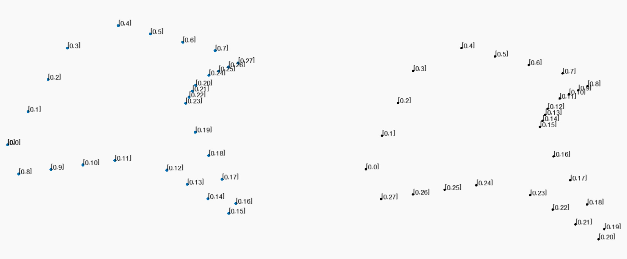
My goal is for the list of points to be read in the order shown in Exhibit 03. Unfortunately, due to being a new user, I can not upload the portion of dynamo script or the test revit file used in the exhibits and had to get creative with the exhibit uploads. Thank you in advance for everyone’s help.
Exhibits:
Important Notes
Revit Version: Revit 2019
Dynamo Packages: Landform Ver. 2016.10.13
Dynamo Experience: Novice
Hi Anthony and welcome,
First off thank you for providing the proper information and clearly explaining your problem.
I have a couple of thoughts for you. Assuming all lines were drawn in the same direction the start point of one line will be the end of another. How are the lines generated? If the lines are user-generated I would get the start and endpoint as you have done (never trust a user to draw everything in one direction). You are only missing a Transpose node between Lis.Creat and Flatten (The link will take you to the online dictionary if you are unfamiliar with how transpose works).
My second thought also has to do with user-generated lines as they may not be drawn in order. Prior to getting the points run your curves through Group Curves. While the primary function of Group Curves from the archilab package is to find curves that are attached to one another it will also order the curves sequentially.
Points.SortPointsAlongCurve from LunchBox will come in handy as an alternative to Group Curves. Take all of your input curves (if you have more than one closed loop they will need to be in separate sublists. Use Group Curves to do this if not already done) and use ByJoinedCurves. This will return a single polyline to be used as a guide sorting the points from start to end.
Thank you. I’ll start experimenting with these suggestions and let you know of any questions or problems I run into.
As to your question on how the lines will be generated, the lines will all be user generated. I foresee most users using the “pick line” draw option to create a number of model lines off of a linked CAD file.
I feel like my lack of experience is preventing me from implementing many of your ideas above. Would you be willing to walk me through the bit of code you provided earlier? I recreated it below and am getting errors on three of the nodes. My hope is that knowing where I am going wrong here will allow me to better analyze where I’m going wrong with your other solutions.
That threw me for a loop when I first saw it but I figured it out quickly enough. You must still be using Dynamo 1.x (You can take a quick look by clicking Help > About in dynamo). 1.x comes standard with Revit 2019. You can manually install Dynamo 2.x from the link below if you want (I do recommend this as there have been many great changes). https://dynamobim.org/download/
If you want to stick with your 1.x version there is another flatten node with only one input. That is the one you will want. Your flatten node is not working because you did not provide the second input. (2.x does not require that input to be filled).
I would highly recommend that you take a look at Introduction | The Dynamo Primer. This is a great resource for getting started. Section 6 is all about lists and that will give you a better understanding of why I am using the flatten node. But in short, it should look like this.
Thank you! Between that and sort points along curve, I was able to create a script that creates a geometry pretty close to that of the originally selected model lines.