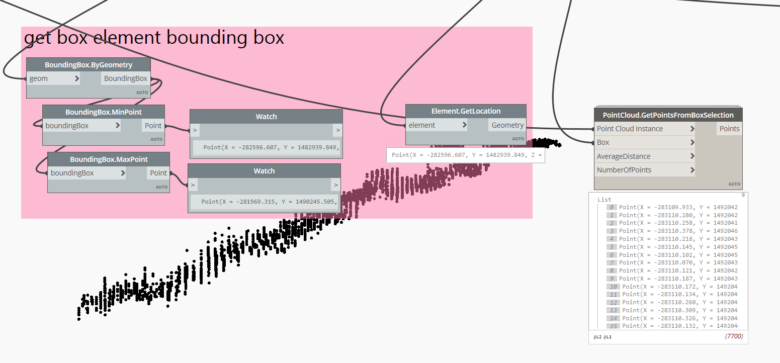
I am trying to filter a subset of points from a pointcloud inside Revit using the node PointCloud.GetPointsFromBoxSelection from the Steamnodes package.
However the points that are being returned are not lying correctly within the 3d selection box. See image 1.
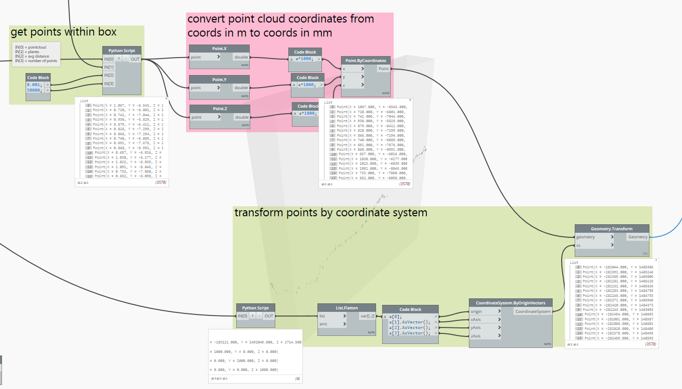
The ‘shape’ of the returned points seems correct. So my guess is that something is going wrong at the transformation of the points, from the pointcloud Coordinate System towards the Model Coordinate System (this happens inside the custom node). See image 2
A quick comparison between the coordinates of the returned points and the bounding box of the box element shows also that the returned points are not within the bounding box. See image 3.
Can somebody help me how to work with this node?
@Julien_Benoit1
check the sastrugi package, there might be something there
https://sites.google.com/view/sastrugi/nodes
Thank you. I had already tried the Sastrugi node Pointcloud.SelectPointsInView, but I can’t get that node to return points. It returns null. I don’t know what I am doing wrong.
After some initial tryouts I liked the Steamnodes node better. At least I got it to return points, albeit in the wrong place. So that’s why I am asking.
@Ewan_Opie can you give an example of how to use the sastrugi node?
*re-bump …
is there anyone out here who has used one of the following nodes…
-Sastrugi PointCloud Select Points in View
-SteamNodes PointCloud.GetPointsFromBoxSelection
…and was able to use them in a successful way?
If so, could you please share with me a small explanation of how you did it?
Would be much appreciated! Thanks in advance…
do you have the latest version of sastrugi?
there was an important update of that node in May
Yes, I believe I downloaded the most recent version around two weeks ago…
A little bit more background about the Steamnodes PointCloud.GetPointsFromBoxSelection node:
The node is a .dyf, so we can have a look inside… it looks like this:
following my hypothesis that something goes wrong at the transformation, lets have a look at the python script at the red arrow. Code looks like this:
I still have to work out what is exactly happening here. I see that the code comes from Konrad Sobon. So @Konrad_K_Sobon maybe you can provide some help?
# Thanks for this code goes to:
# Copyright(c) 2016, Konrad K Sobon
# @arch_laboratory, http://archi-lab.net

# Import Element wrapper extension methods
import clr
clr.AddReference("RevitNodes")
import Revit
clr.ImportExtensions(Revit.Elements)
# Import geometry conversion extension methods
clr.ImportExtensions(Revit.GeometryConversion)

# Import DocumentManager and TransactionManager
clr.AddReference("RevitServices")
import RevitServices
from RevitServices.Persistence import DocumentManager
from RevitServices.Transactions import TransactionManager
doc = DocumentManager.Instance.CurrentDBDocument

# Import RevitAPI
clr.AddReference("RevitAPI")
import Autodesk
from Autodesk.Revit.DB import *

import sys
pyt_path = r'C:\Program Files (x86)\IronPython 2.7\Lib'
sys.path.append(pyt_path)

#The inputs to this node will be stored as a list in the IN variable.
dataEnteringNode = IN

def ProcessList(_func, _list):
    return map( lambda x: ProcessList(_func, x) if type(x)==list else _func(x), _list )

def Unwrap(item):
	return UnwrapElement(item)

def GetTransform(e):
	return e.GetTotalTransform().Origin.ToPoint()
def GetBasisX(e):
	return e.GetTotalTransform().BasisX.ToPoint()
def GetBasisY(e):
	return e.GetTotalTransform().BasisY.ToPoint()
def GetBasisZ(e):
	return e.GetTotalTransform().BasisZ.ToPoint()

if isinstance(IN[0], list):
	elements = ProcessList(Unwrap, IN[0])
else:
	elements = [Unwrap(IN[0])]

try:
	errorReport = None
	output = ProcessList(GetTransform, elements),ProcessList(GetBasisX, elements),ProcessList(GetBasisY, elements),ProcessList(GetBasisZ, elements)
except:
	# if error accurs anywhere in the process catch it
	import traceback
	errorReport = traceback.format_exc()

#Assign your output to the OUT variable
if errorReport == None:
	OUT = output
else:
	OUT = errorReport
Here is a preview of what happens when I use the Sastrugi node … cant get it to work …

maybe feed a bounding box in the point sample size input?
I am getting a little further about what happens inside the Steamnodes PointCloud.GetPointsFromBoxSelection .dyf.
The python script at the red arrow returns 4 points.
The first point is probably the pointcloud’s (transformed) origin location.
This numbers matches with what I see in Revit.
The next three points are probably scaled vectors (there components are 1000), which might have to do with a scale factor from meters to millimeters.
Thanks! that looked helpful, but the vid seems outdated.
It doesnt seem to work the same way as the current version.
In the vid he picks a number of points.
In my version, i have to drag-select a region, bottom left to top right.
If i just click once then the second popup comes immediately, asking to select the pointcloud instance.
I believe I have it. It was a meter / millimeter mismatch.
The filtered points, coming out of the first python script in the dyf, are being returned in METER coordinates. So these are pretty small values. These are point coordinates relative to the pointcloud origin.
The current location of the pointcloud in the model is a value in MILLIMETERS:

If we transform the points towards the location of the pointcloud in the model, then a value in meters is being added to a value in millimeters. Resulting in a too small value.
So what I had to do is:
-
first convert the filtered points from meter coordinates to millimeter coordinates, by multiplying their XYZ components times 1000.
-
And only then feeding them into the transformation module.
After that, the points are in the right place. They lie within the selection box!
Hooray!
2 Likes
Hi J, are you able to share the Python code you built for the transformation part of this script. I seem to be getting points that are in mm correctly but are bunched up in one place. Their doesn’t seem to be anymore than 10mm between them all. When I scale by a 1000 it looks correct but the coordinates are silly large. .
Sorry I dont have the code available anymore. Were you able to figure it out in the meantime?
I did thanks, it was my mistake, I misunderstood what you were describing. It works a treat.