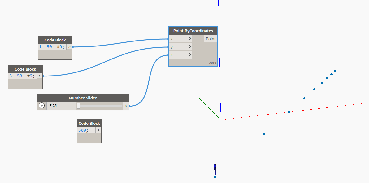
Is there any way , you can have a list of points & drag each of them individually independent of others ? for example lets 10 points in a list even if created with point by coordinates , is it possible to control their location manually after generation in 3d preview. so far it does not happen.
as of now the points move with one reference, or as one set! any way it is possible to move them independently. any suggestion would be appreciated. Thanks
Hi @sachin.menon !
You can translate them.
If you d’ont need to move each one just use
List.GetItemAtIndex .
Hi @Francois_Labonne, thanks for the reply.
Actually i have a bigger workflow ,wherein i already have quite a bit of points for each area/surface/rooms based on certain design inputs. However there are certain sections of the room/area where i want to basically move those points to account for coverage . Hence i wanted to give user the option to manually move them as required .
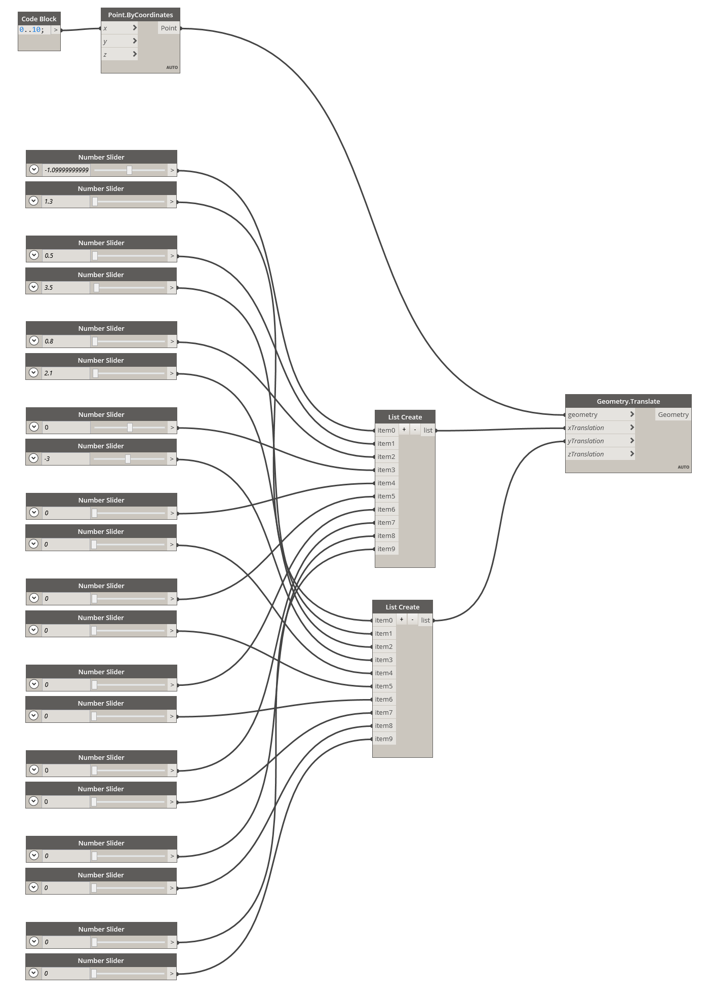
as you can see in attached image , i am trying to explore if the direct preview manipulation can be applied to selected points without much tinkering with existing workflows . i know & have tested the dynashape package( does not suit Our workflow/requirement) , which gives flexibility in preview manipulation, just wondering if any sort inbuilt functionality can provide the same as well, without loosing existing mechanism or attained results.
Thanks again
I agree my graph is not handy…
I am afraid there is not such inbuilt functionality in Dynamo.
You can use Revit as a preview, in there it is easy to move any element, you can copy it to another view eventually to not loose your initial data…But it is maybe a workflow that don’t suit your need.
The Data.Remember node may help you maybe.
Maybe you should start another thread, with more explicit title and tags.
Hi Jacob,
In our current workflow , i am able to get the number of devices required per room easily with the default nodes & no external packages. Dynashape requires the excel based template & also it was slower when we had tested & limited movement of the generated points. we had reached out to Long Nguyen & he had mentioned that it was due to fact that the non convex polygon are not part of its current functionality. Due to all of this , had decided to opt for default nodes. The current set up does works fine almost covers the rooms & with help of sliders can be used to increase number of devices. just to cover the last 5-10% i was trying to see if any one had done anything for direct manipulation .
thanks again.
hmmm… interesting… what are you actually solving for here? Minimum number of points to provide ‘coverage’ to the space?
Basically trying to provide/place number of devices for MEP based on room/space area as per engineering calculations in model ( for each room we already have required numbers ), but the numbers are more like thumb rule defined for 4 sided rooms (rectangle or square). obviously in an actual project we have so many asymmetrical rooms like “V”, “C”, "L " shaped rooms as well, plus on top of that they are not always oriented in XY axis .
hence we are trying to accommodate the number of devices (+5% )just to ensure max coverage area for the devices as per fire safety protocols. however due to geometry of such rooms some corners miss out by few inches . Hence we kind of thought that ,if user could be provided with manual /direct manipulation option if possible , so that BIM engineers can map out the location while running the script , this would help them to account for coordination aspects as well.
Hmmm… might be a good exercise for Generative Design as it would allow optimization of count instead of that 5% buffer you’re adding.
I think this would work for any shape as you appear to be keeping a ‘row’ layout.
- Find the untrimmed diagonal of the space by using a vector on the bounding box from min point to max point, pull the length as this will serve as a primary dimension.
- Draw a line from the parameter (-0.5,-0.5) of the space that is 2.5x the diagonal on a variable vector angle.
- Rotate the vector 90 degrees, translate the line 1.25x the diagonal on the resulting vector.
- Rotate the vector -90 and translate the vector by along that vector using a range from 0 to 2.5x the diagonal, stepping by a variable for row spacing.
- Trim the resulting lines by intersecting with the space’s surface.
- Get the length of the resulting lines, divide that by the max element spacing, then use parameterized ranges to create points along each line by that count (0…1…#count).
- Create circles at each point, convert those to a surface, union them. Then subtract the union surface from the space surface, and get the area of the result. Divide that by the overall area of the surface to get a number between 0 and 1. Then set a watch node to the remaining surface area and name it ‘uncovered area (min)’.
- Test if the area > 0, return 1 if true, 0 if not. Set a watch node off of this and rename it ‘complete result (min)’.
- Take the X and Y components of the Vector from step 1 and divide both by the lesser of row spacing or the max element spacing. Sum those two values. Divide the count of fixtures by this value giving you a value between 0 and 1. Set a watch node off this value and name it ‘fixture ratio (min)’
- Add in whatever method you have for placing the fixtures themselves here, but behind a Data.Gate node.
- Make sure all the watch nodes are set, and be sure that your remember and gate nodes are in place (I skipped the remember node along with the gathering of the room surface), and that all 3 watch nodes are marked ‘as input’.
Generative Design would then take a space and optimize the angle of the rows, and the row spacing for minimal count. Follow
Best practices and recommendations for testing as you go, and add in any edge case handling (what if a surface is too small to catch a circle? what if my fixture doesn’t have line of sight to part of the area it is covering? Etc…) and you should be good to go.
Hi Jacob,
Generative design too was my first thought as the workflow was pretty straight forward . i was using revit 2019 & dynamo 2.0.2 with refinery package(0.4.26) as the project team is currently using 2019 model. however i faced issues with the Refinery not giving any previews while it says 10 or 20 iteration etc. generated ( but nothing is visible) & also at times refinery gets stuck in a loop & would not respond even with generation size for 20 iterations. so had to restart revit multiple times. I had gone through some of the post where in you have cleared out same kind of issues for other users but it did not work for me or my colleague. I also did download 0.6.2 release & it would install, but would not show up in dynamo 2.0.2 or dynamo 2.3 in revit 2020. so due to these issue, I thought better to go with the current workflow & once refinery is working fine or the glitches are resolved at our my end then perhaps switch to generative design workflow.
Thanks
That’s too bad as this is a great potential use case. Would be worth testing in 2021, and if that does not work feel free to share the graph and I’ll see if I can make it work.
Yes totally agree. the script can be reused perhaps for other MEP device automation such as sprinklers, lighting fixtures etc. with minimum modification or updates. we will definitely give refinery a shot with revit 2021 some time soon, hopefully there wont be any bugs/glitches .Really appreciate you taking your time & providing these valuable insights, we will keep you posted in how it fares.
Thanks again
1 Like
Hi Jacob,
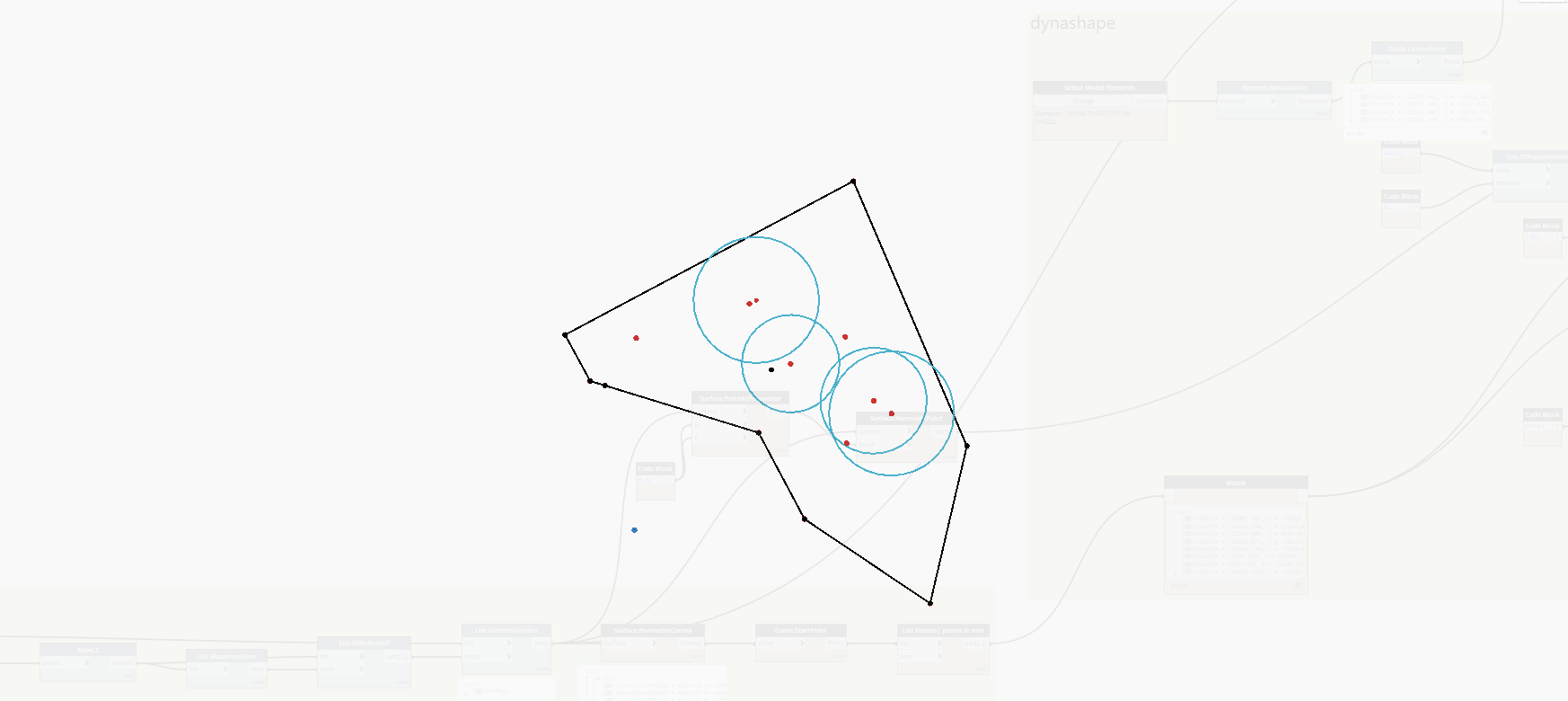
i managed to test out the workflow in revit 2021 with refinery, it does work smoothly & without glitches compared to revit 2020. However the project teams wants something more interactive, similar to direct preview as we had discussed earlier.
Hence i went back to DynaShape Package, tried a bit of preview manipulation using DynaShape nodes.
workflow:
-
created small surface from space
-
manually placed 4-5 few random circles within the space in revit.
-
used DynaShape nodes to see if i am able to move them freely , which i am able to achieve.
however the points seems to move along z axis as well, even though i have pulled the points onto the surface.
i have attached images of the graph, along with images of the preview. it might be something silly or very basic that i might have missed here. But would really appreciate , if you can point out what am i doing wrong or if i missed anything. Is the Goals & geometry binders the issue or the something else entirely?
Thanks
Perhaps try bringing the ‘best performing’ study from Generative Design back into Dynamo so the team can play with it there? This is a bit of a unique case as just about every other bit of feedback I get around these types of tools is that users don’t want any more input/manipulation, they just want the computer to ‘do this’ for them.
Reviewing the graph, my first thought is that the Goals and Binders is the issue, but I have not played with this package in about 2 years or so. I’ll try and have a look later today. What time zone are you located in?
For me its IST( Indian standard time), i think late evening time for me would be something more convenient & adjusted to your time as well , it would be morning hours for you. I am guessing yours is EST?