I got an interesting question via email today and I thought I’d share it here:
I have a problem with dividing surface in Revit, and I think I partially found the solution in this topic you wrote:
autodeskvasari.com/forum/topics/parameter-values-from-image-for-dynamo
So here is what I want to achieve. All I want to do is to divide surface with adapitve 3 point component in an irregular way. But, I want to manipulate this distribution from the center not the begining of my surface. Is it possible to do? Should I just change the function sin(v*pi/2) to some other? To be precise, because I have been trying out other functions: I want it to be denser in the middle and wider on the ends. I have managed to make it denser on the ends, but still it’s not my goal.
And here’s the answer:
You are correct - you only need to find the correct formula. If you look at a sine wave, you’ll want to use the first half of the entire cycle to get a list of values that is packed more densely in the middle. Hence, you’ll need to start with Sin(xpi) where x can have values between 0 and 1. However, the resulting y values will only increase until x=0.5 (or pi/2) (which will give you a value of 1), after that they will decrease again. But if you combine your sine formula with a condition, you can make values of x > 0.5 produce results that are greater than 1 by adding 1 to their inversion (1-y), like so: 1+1-Sin(xpi). Since this will give us a range of y values between 0 and 2 (and we want to have a range of 0 to 1 for creating UV coordinates), the complete formula would have to look like this: if(n>0.5,1+1-Sin(npi),Sin(npi))/2
I would have liked to add some annotated graphs, but the computer in front of me has neither a grapher nor Photoshop installed. I hope the above explanation is sufficient nonetheless.
You will need components from the following packages:
- Increment/Decrement By 1
- Normalization
- Simple Patterning
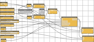
And some images…

 The building is the colored one - (Yamaha). From Revit I created the mass, then the divided surface, in a Family ambient.