Hello,
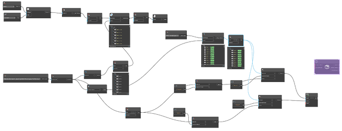
I’m working on a Dynamo script for an opening family.
The goal is to replace the Generic Model BWIC family, which comes from a linked MEP model, with an Opening family placed directly on the wall in my own model.
First, I used the Get All Elements from Linked Model node to retrieve the Generic Models from the MEP link.
Then, I tried to find the intersections with elements in the Wall category and place the Opening family at those intersection points.
However, the Geometry.Intersect node is not working as expected. I’ve tried several different methods, but haven’t had success so far.
Could anyone assist with this issue?
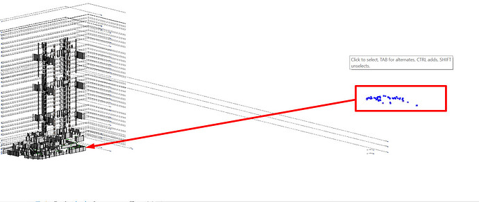
Likely that the internal origin of the two models differs, and as such you have to transform the geometry from the link by the coordinate system of the link instance.
Would need sample models and graph to confirm though.
I’ve now transferred the opening slab family from the linked model into my current model, but the intersection with the wall is still not detected – it returns an empty list.
I also tried using the bounding box option, but that didn’t work either.
If I can add voids at the intersection points with the wall or replace the transferred family with an opening family, that should be sufficient. Any help on this would be greatly appreciated.
Do you have solids from Element.Solids on both the wall and the void families?
I tried it in two different ways.
In the first file, I worked with a linked MEP model and tried to replace the MEP openings with my own void-based opening family. But it didn’t work.
In the second file, I imported the MEP openings directly into the model, so there’s no linked file in this one. Then I again tried to place my own opening family at the intersections with the walls – but that didn’t work either.
When that also failed, I tried placing my opening family for all MEP openings regardless of whether they intersect with the walls or not but that didn’t work either.
BWIC_Without lik.dyn (46.2 KB)
BWIC_With link.dyn (42.3 KB)
link file:
Pin all the node preview bubbles before taking a screenshot. We need to see what you’re actually dealing with. Also, make sure you’re zoomed in enough that the node names are visible when you take the screenshot. Your first image is illegible but the second we can read.
Thank you for your feedback. I am resending the first image.
First thing that catches my eye is flattening with cross-product lacing. This isn’t doing anything in most cases and is actually hurting you. Best thing to do is get Element.Solids and union those together (per element). Once you have a single solid per element, you can flatten that to a single list if you need to (it may already be one).
I removed the cross-product lacing and tried both Solid.Union and Solid.ByUnion, but it still doesn’t return any intersections.
So the issue here isn’t with the lacing type (it was right before), but with the dataset.
There are N walls in the view you have for arch.rvt. This results in a nested list of geometries for each wall. Filtering to just the view is good as it will limit the scope relative to the entire model.
Looking at the mechanical elements, there are 170 generic model families in the link. They are not filtered to the view though, and as such you have some elements are up at elevation 11413, but no selected wall is higher than 4725… as such attempting to intersect the mechanical element with the selection will always result in an empty list.
That lack of intersection when looking at just the elevations is exponentially scaled across the X and Y axis as well. This makes sense though as each opening element should only interact with one wall, but a wall might have multiple openings.
From what I can see, the empty lists you’re seeing are a good thing as a result.
If you’re talking about the lacing with the Flatten node I disagree. The lacing may not be the causing the lack of intersections, but it’s making things harder for no reason. Flattening those sublists isn’t changing the structure at all and having (potentially) more than one geometry per element is just going to add more layers of confusion. Cleaning that up should make it more apparent as to what’s happening.
Using cross-product lacing for Geometry.Intersect (which may be what Jacob is referring to above) was the right idea. Now you’re no longer checking each generic model against each wall.
You also haven’t done anything with the wall section. We still can’t see what that data looks like and you still have it flattening the list rather than unioning the geometry. The simpler your data the simpler the logic needed to accomplish your task.
Another simple check you can do: view the solids in the geometry background. Does Dynamo even show the generic model geometry intersecting the walls? Does it look correct?
The cross product on geometry intersect was what I was referring to.
Solid.ByUnion to remove the ‘list’ nature of content from Element.Solids would also help. Otherwise there is an extra set of solids to intersect. List.Flatten can also do the trick, but in reviewing the dataset it’s messier that way so unioning every ‘list’ of solids into one solid makes sense.
The Element.Geometry node is also making more complex for the same reason. Why test if the three solids and six curves produced by a elements geometry when all you care about is the total sum of all solids? I’d swap that for Element.Solids and Solid.Union as well for the resulting reduction in number of tests to perform.
There are also a few walls with no geometry in the view - filtering those out is also a good idea.
1 Like
Here is a preliminary solution using Python (FilteredElementCollector with a combination of Quick and Slow filters).
The result is a list of type
[
    [hostWall, [lst_lnk_wall_openning],
    [hostWall, [lst_lnk_wall_openning]
]
code Python (IronPython3 or PythonNet3)
import clr
import sys
import math
import System
from System.Collections.Generic import List

clr.AddReference('ProtoGeometry')
from Autodesk.DesignScript.Geometry import *

clr.AddReference('RevitAPI')
import Autodesk
import Autodesk.Revit.DB as DB
from Autodesk.Revit.DB import *

clr.AddReference('RevitNodes')
import Revit
clr.ImportExtensions(Revit.GeometryConversion)

clr.AddReference('RevitServices')
import RevitServices
from RevitServices.Persistence import DocumentManager
from RevitServices.Transactions import TransactionManager
doc = DocumentManager.Instance.CurrentDBDocument


def createSphere(center, radius=0.328):
    frame = Frame(center, XYZ.BasisX, XYZ.BasisY, XYZ.BasisZ)
    arc = Arc.Create(  center - radius * XYZ.BasisZ, center + radius * XYZ.BasisZ, center + radius * XYZ.BasisX )
    line = Line.CreateBound(arc.GetEndPoint( 1 ), arc.GetEndPoint( 0 ) )
    halfCircle = CurveLoop()
    halfCircle.Append( arc )
    halfCircle.Append( line )
    sphere = GeometryCreationUtilities.CreateRevolvedGeometry(frame, List[CurveLoop]([halfCircle ]) , 0, 2 * math.pi)
    return sphere


linkInstance = UnwrapElement(IN[0])
tf = linkInstance.GetTotalTransform()
lnkDoc = linkInstance.GetLinkDocument()
#
rule = ParameterFilterRuleFactory.CreateContainsRule(ElementId(BuiltInParameter.ALL_MODEL_TYPE_NAME), "For Review")
filter_name = ElementParameterFilter(rule)
#
all_link_openings = FilteredElementCollector(lnkDoc).OfCategory(BuiltInCategory.OST_GenericModel).WherePasses(filter_name)\
                        .WhereElementIsNotElementType().ToElements()

dict_wallIds_lnkOpenning = {}

for lnk_elem in all_link_openings:
    bbx = lnk_elem.get_BoundingBox(None)
    midPt = tf.OfPoint((bbx.Min + bbx.Max) / 2)
    # bounding box filter
    newBBx = BoundingBoxXYZ()
    newBBx.Min = midPt - XYZ(1,1,1)
    newBBx.Max = midPt + XYZ(1,1,1)
    myOutLn  = Outline(newBBx.Min, newBBx.Max)
    filterBbxInters = BoundingBoxIntersectsFilter(myOutLn)
    # solid filter
    solid = createSphere(midPt)
    filterSolid = ElementIntersectsSolidFilter(solid)
    #
    host_wall = FilteredElementCollector(doc).OfClass(Wall).WherePasses(filterBbxInters).WherePasses(filterSolid).FirstElement()
    if host_wall is not None:
        dict_wallIds_lnkOpenning.setdefault(host_wall.Id, []).append(lnk_elem)
    solid.Dispose()

# convert dict to list
result_wall_linkOpenning = [[doc.GetElement(keyId), lstOpenings] for keyId, lstOpenings in dict_wallIds_lnkOpenning.items()]
#
OUT = result_wall_linkOpenning
3 Likes
Hello,
Thank you very much for the Python script you shared, it was really helpful. Thanks to it, the intersect node in Dynamo is now working. However, I am facing two issues:
1. MEP opening location:
I am having trouble finding the correct location of MEP elements intersecting with the wall. I have tried using Family Instance Location, Solid Centroid, and BoundingBox, but none of them gave accurate results.Could you help me to fix this?
2. Opening family placement:
The opening family I am trying to place on the wall is not positioned correctly. The family’s base point falls on a different spot and it does not take the wall thickness into account. Because of this, I couldn’t test if it actually cuts the wall. In another test I tried, it did not cut the void.
Could you please help me with these two points (finding the correct MEP location and placing the void family correctly on the wall)?
Thanks in advance.
Hi,
The internal & project coordinates of your linked model are probably not aligned with your host model.
- Try to retrieve the transformation from your Revitlink instance and apply it to your points
OR
- get the points directly from the Python script (variable “midPt”)
Here is an alternative version that calculates the centroid of the linked openings.
import clr
import sys
import math
import System
from System.Collections.Generic import List

clr.AddReference('ProtoGeometry')
from Autodesk.DesignScript.Geometry import *

clr.AddReference('RevitAPI')
import Autodesk
import Autodesk.Revit.DB as DB
from Autodesk.Revit.DB import *

clr.AddReference('RevitNodes')
import Revit
clr.ImportExtensions(Revit.GeometryConversion)

clr.AddReference('RevitServices')
import RevitServices
from RevitServices.Persistence import DocumentManager
from RevitServices.Transactions import TransactionManager
doc = DocumentManager.Instance.CurrentDBDocument


def get_solid(elem, tf):
    opt = Options()
    for geo in elem.get_Geometry(opt):
        if isinstance(geo, DB.GeometryInstance):
            for geoI in geo.GetInstanceGeometry():
                if isinstance(geoI, DB.Solid) and geoI.Volume > 0.01:
                    return DB.SolidUtils.CreateTransformed(geoI, tf)

    return None

linkInstance = UnwrapElement(IN[0])
tf = linkInstance.GetTotalTransform()
lnkDoc = linkInstance.GetLinkDocument()
#
rule = ParameterFilterRuleFactory.CreateContainsRule(ElementId(BuiltInParameter.ALL_MODEL_TYPE_NAME), "For Review")
filter_name = ElementParameterFilter(rule)
#
all_link_openings = FilteredElementCollector(lnkDoc).OfCategory(BuiltInCategory.OST_GenericModel).WherePasses(filter_name)\
                        .WhereElementIsNotElementType().ToElements()

dict_wallIds_lnkOpenning = {}

for lnk_elem in all_link_openings:
    solid = get_solid(lnk_elem, tf)
    if solid is not None:
        centroid = solid.ComputeCentroid()
        # bounding box filter
        newBBx = BoundingBoxXYZ()
        newBBx.Min = centroid - XYZ(1,1,1)
        newBBx.Max = centroid + XYZ(1,1,1)
        myOutLn  = Outline(newBBx.Min, newBBx.Max)
        filterBbxInters = BoundingBoxIntersectsFilter(myOutLn)
        # solid filter
        filterSolid = ElementIntersectsSolidFilter(solid)
        #
        host_wall = FilteredElementCollector(doc).OfClass(Wall).WherePasses(filterBbxInters).WherePasses(filterSolid).FirstElement()
        if host_wall is not None:
            dict_wallIds_lnkOpenning.setdefault(host_wall.Id, []).append([lnk_elem, centroid.ToPoint()])
        solid.Dispose()

# convert dict to list
result_wall_linkOpenning = [[doc.GetElement(keyId), lstOpenings] for keyId, lstOpenings in dict_wallIds_lnkOpenning.items()]
#
OUT = result_wall_linkOpenning
1 Like


