Getting the geometry on the file you provided isn’t an issue. This makes me think that it’s something other than the face based families is creating the issue.
If it helps this will remove the sockets. All python (and the real effort) is out of the Element.Geometry+ node in the Clockwork Package.

2 Likes
I tried the phases method myself and it works great for cuboid openings of the wall. But not for yours because…? Bugs?
Here’s what I did:
New Temporary phase:

Dynamo looking like this:

And effectively the sockets were put in the future phase. Revit handles that with filling the wall’s void with new solids:
And in Revit they look ok. So you would imagine that joining them with the rest of the wall is all that you need now, but:

In Dynamo these solids look differently

1 Like
Because the solid was built as a void geometry, and Dynamo doesn’t consider things as solids or voids, only as geometry, all of which can be unioned or differenced.
1 Like
@jacob.small
It works as expected with my test with rectangular face-based voids, but not with these.

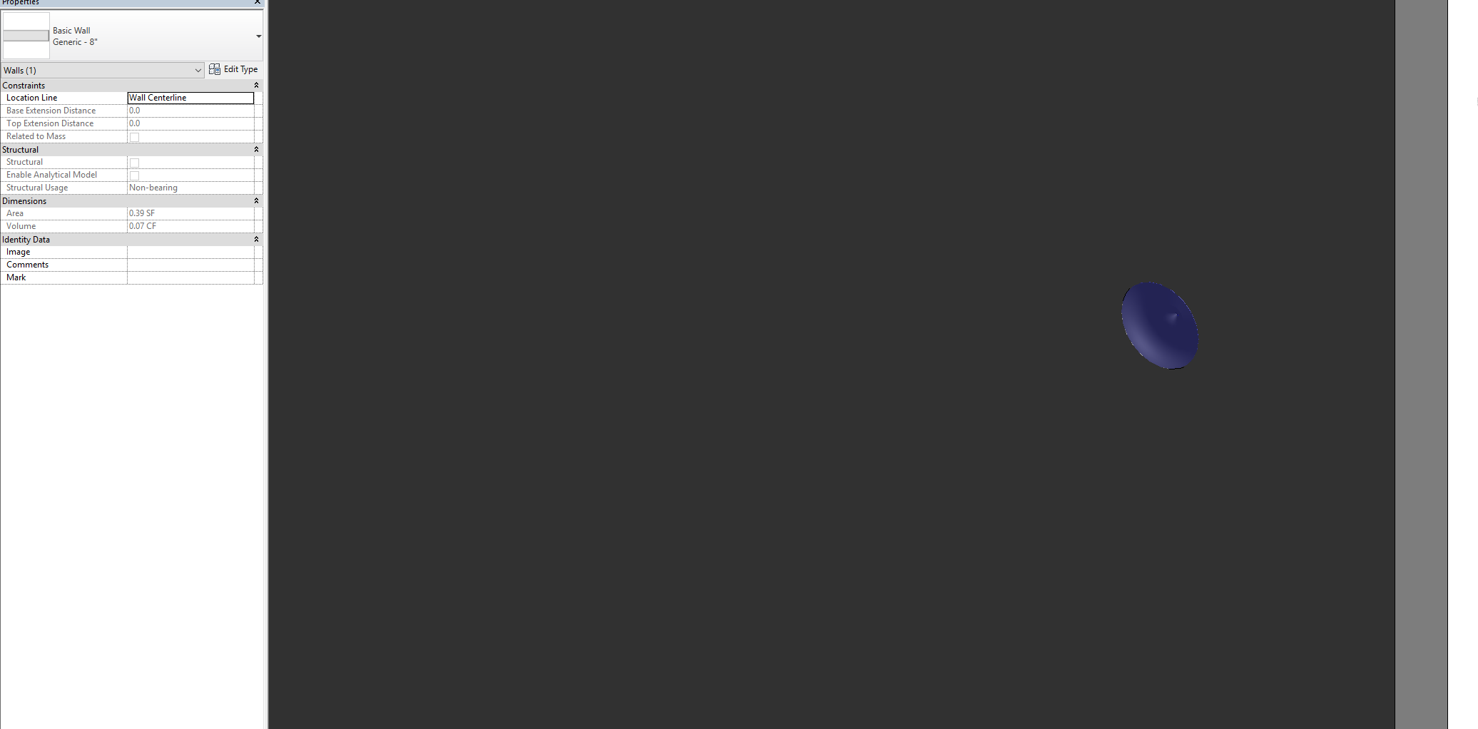
This is the shape in Dynamo.

This is the face-based family.

This is how it looks on the wall.
There is some problem with the geometry conversion here.
It works as expected with a rectangular extrusion:


1 Like