Hi everyone, I have just started using Dynamo for Civil 3D and after spending many hours I think I finally am in a right place to share my problem. I want to loft the rail vehicle clearance profiles which are already placed on the track. From what I learned from the internet, I think I have reached to some point by due to lack of my knowledge I cannot go further.
There are few questions I need your help if you would…
1- As you can see in my script, I have picked two first profiles and made a solid out of them and after many tries, I finally dont have a warning but still I cannot preview my output in Dynamo.
2- I want to add all my profiles at once so I wouldnt need to make scripts over and again. I have placed them in one layer but I dont know how to import and use them all inside Dynamo. I saw a short video from Autodesk on this exact matter but couldnt find any details although I searched Autodesk University top to the bottom.
Starting minute 1:30
3- What would be the best practice to export my output geometry to Civil 3D?
Thank you all in advance, any help would be appreciated. My level of knowledge in dynamo is near to zero.
Hi,
Just before starting, how did you place the real vehicle clearance profiles along the track ?
The principle here is to have a clearance profile, that you can place along the track, tacking into account cant, at a certain interval and then generate a solid that you can use for clash detection for example.
You already have the pofiles placed on the track, you just need to loft them to create the solid and you can send that back to Civil 3D using the Object.ByGeometry node.
Now, the tricky and repetitive thing here is the placement of the profiles (hence why my initial queston). I will advice to actually use Dynamo for this :
- Start from a clearance profile (block definition, polyline whatever) and get its geometry into Dynamo (you will be creating a Dynamo Proxy)
- You now need to get the coordinate systems that will be used to place this profiles. This will be the “hardest” part of the script and you will probably need to do some geometry work with vectors or coordinate systems. Assuming you are working with corridor objects, you will need to get the coordinate system by stations -you can define the distance between stations - taking into account the cant (you can use the AlignmentExtensions.GetCantInfoAtStation node from the C3D Toolkit). If you don’t have a corridor with applied cant but rather polylines for example representing your track, you can use Dynamo to figure out the cant too
- Once you get the coordinate systems right, you just need to place your profile along thos coordinate systems and you will have the profiles along your track every X distance
- Create a solid by loft (this might take a while depending on the number of profiles you have)
- Send it to Civil 3D using the Object.bygeometry node
There are examples out there of how to place blocks or geometry along a linear infrastructure. The principle here is the same so you can use those examples as a starting point. See this example : Place Block along Rail with CANT
Hi @david_licona ,
Thanks a lot for replying and answering very thoroughly. I see you have explained me the actual proper way of doing the task.
As of the limitations I have. for not having any alignments or corridors, no cant calculations however I proposed so but since all the project aspects were designed I suppose in Cadworks or some other softwares, time is another bet to take into account.
As you can see in the video, I can loft them one by one which was initially the idea but I think this is where the automation plays a huge role.
So, is there any way I can automate this manually lofting?
Thanks in advance
Hi @jefili9693,
So how did you get them at the correct place? Did you did it manually or got the file like that already ? Because as I said if you have 3D polylines representing your tracks then you can use Dynamo for all !
For your current workflow, you can use the selection nodes on the autocad shelf to select them all by layer using the all objects on layer node :
You will need to make sure the profiles are in the correct order, following each other one by one. I don’t know that will be the case automatically as I asume you will get them as they were added to the database or maybe even randomly. To make sure they are in order you can use some list nodes such as the sort by key. There are many examples on the forum such as this one : Organized cogopoint list by number
There are also some dynamo community conversations talking about lists: 06 - Process data effectively using list levels - Dec 2020 - YouTube
You can then loft for getting the solids. As I say this may take some time depending on the number of profiles you have.
2 Likes
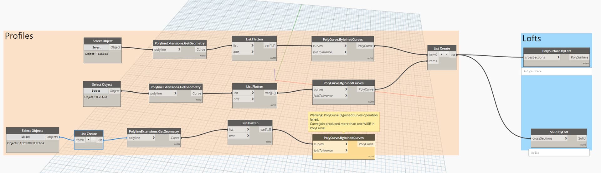
Thanks again @david_licona really appreciate you following my problem. I followed your path (at least thats what I think) and I get this warning.
And even when I tried the
Object.ByGeometry node as you advised earlier, for only two profiles, the node shows null.
Thanks in advance
how did you get them at the correct place?
I got the file like this. I have already contacted the person asking about it and waiting for his reply.
One issue is that not all the profiles are the same. I checked their area and they differ. So, if even I try dynamo to place the profiles on track, I may need to define a parameter which I dont know if possible in dynamo.
By All Objects on Layer I put two profiles in one layer and tried to check if the error is due to the profie ordering, it gives me the same warning.
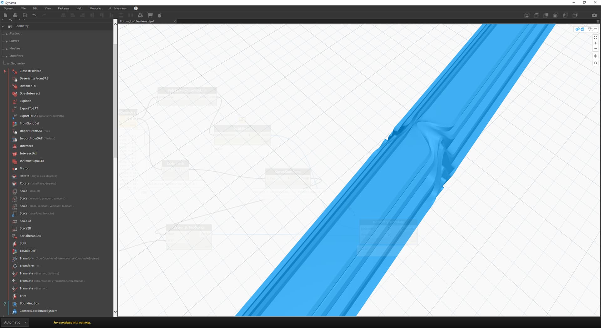
So after surfing the internet, I tried levels and the error is gone but strange thing (for a newbie  ) I cannot see my solid neither in Dynamo nor in my dwg.
Forgive me if I don’t know the very basics but I’m here to learn.
Thank you
I strongly recommend going through the Primer first before trying your hand at some graph making. It takes some effort but totally worth it for your adoption of Dynamo.
Can you share the dwg file ? I see some problems in your graph. The list create nodes are redundant. You already have a list of the cross sections since the beginning. List create would be when you want to combine different elements or different lists into a sole list. Can you also show the output of the second list create node ? I think you are not using all of the sections but not entirely sure.
To go to the preview of a Dynamo node (your solid by loft) select the node and then click zoom to fit on the top right corner, it will zoom the graphical space to the selected nodes geometry preview.
The output of object by geometry will not be visible in dynamo but only in Civil 3D. You can even plug in a DocumentExtensions.ObjectHandle node after so you can get the handles of the objects being created and then zoom in Civil 3D to those objects to verify quickly your solids. See this article : Selecting or zooming to an entity based on its handle identification code | AutoCAD | Autodesk Knowledge Network
2 Likes
Loft.dyn (21.9 KB)
Size of the dwg file is more than 8mbs and it doesnt allow me to upload it here. I would be happy to share it somewhere else.
Thanks.
I went through primer but skimming, due to shortage of time but I will definitely go again thoroughly.
You can use wetransfer, dropbox… or you can simplify the drawing leaving by removing elements leaving just enough profiles to test the concept
Hi @david_licona,
Sorry for replying late, I simplified the dwg and am attatching it here. If you could please have a look at it.
Thank you 
Loft.dwg (4.3 MB)
Ok so I did a quick script and I am getting something weird on the solid. I will need to take some more time to go more deeply on this. At the moment I was just lofting as you were, but will probably need to construct “guiding curves” and loft using them to avoid this weird thing.
Any geometry guy out there has had something similar when creating solids by loft ? @jacob.small maybe  ?
?
I also noticed that the all objects on layer is giving some problems I think it is because of the special characters. The file input looks like is coming from toporail is this the case ?
Yes, this usually prevents issues like this.
1 Like
The guide curves are pretty easy to build if you have a consistent geometry. Something like Curve.PointAtParameter(crv@L1<1>, [0,0.5]); will usually do the trick. This may be ideal for inconsistent geometry too if you have a fairly consistent blend of shapes; Be careful that your coordinate systems don’t ‘flip’ though, as is known to happen with some aspects of the geometry kernel.
1 Like
Hi @david_licona, thanks for your time.
I will be waiting for your discovery of how to do it.
Yeah you are right I got it from the client that its from Toporail and that might be the biggest problem here.
I created surfaces using Sverchok in Blender but I would really love to know the way of doing it in Dynamo
Thanks
Hi @jefili9693
Try this, select only profiles, no path. For me it works.
Loft Poly3D2Solid.dyn (36.8 KB)
2 Likes
Hi @Ge0rges,
Thanks for replying to my post. I used your file and what I get is the broken pieces of soild geometry as shown in the photos.
Here, in the below dwg, I only used the profiles in layer ‘1’.
Loft_880_RS_FbE2023-Projekt_EBV3Soll_2_1_23194_81d8c61a.dwg (6.9 MB)
Thanks in advance