How could I use dynamo to get the center line of parallel lines from cad?
Now I have obtained the center line of the two end points of the parallel line and generated the wall, but it is not completed smoothly every time. The completion status is as shown in the picture…
I have found that the drawing order of lines in CAD is closely related to the form of the lines, but I still cannot successfully complete the pairing of double lines every time to obtain the center line. Can anyone help?
@Draxl_Andreas Thank you, sir.
However, I am currently using the script you provided for DWG testing, and the results are still not satisfactory.
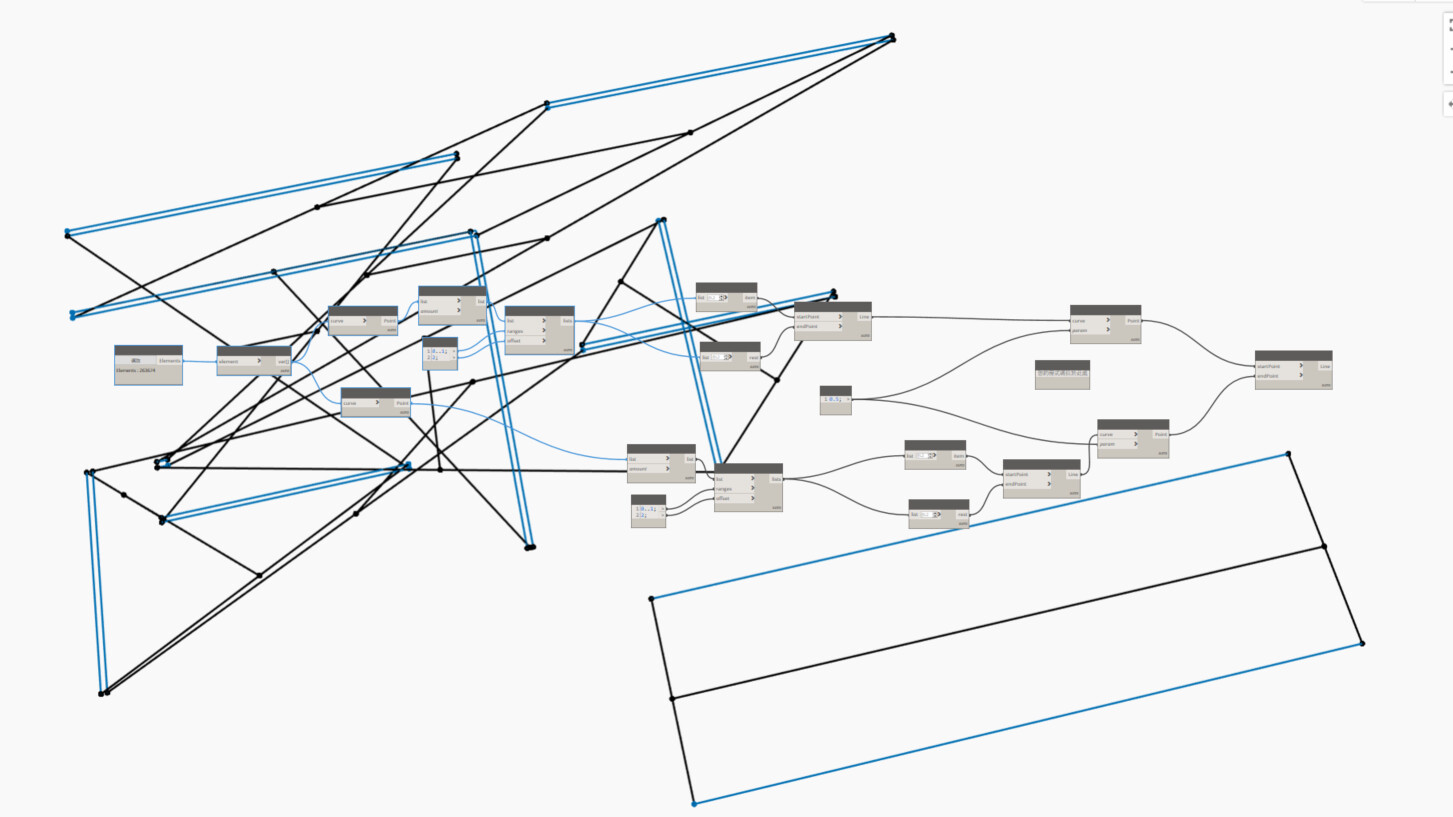
I found that before the points were matched, the lines were what I expected the results to be, but after going through “List.Sublists”, the order of arrangement did not preserve the points at the beginning and end of the lines.
The issues confuse me very much and I’m really eager to know how to successfully achieve the desired results.
Attachment provides the test results and DWG files.
Please help again…
It is a semi-automatic solution (lack of skills on my part to do everything automated) rather than an entirely automated solution where all special cases must be eliminated.