Creation of Structural Framing with Dynamo

Hello gentlemen,
I’m trying to place Structural framing elements using the Revit family from default Revit template and Dynamo node StructuralFraming.BeamByCurve. But the typical issue that I face from time to time is a Curve orientation. I know from different Rhino forums that curve can have only direction regarding this meaning. But I pretty much sure that curves have not only directions what you can get from a Curve tangent parameter Node in Dynamo. Even in dynamo itself you can get curve normal parameter which, as I understand, describes the orientation of curves.


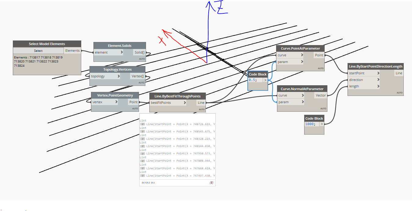
In this case I’m dealing with IFC geometry so with small manipulations I get the Ref lines again.
As you can see here normal of curves pointing in some direction that is parallel to the X axis. And in this case the Str framing comes with correct orientation.

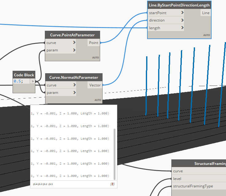
But when I proceed to geometry intersect Node, in order to get curve line for my Structural Framing, I got nurbs curves with normal pointed along Z axis.

And now some framing will be placed not correct:
image
The cross section rotation parameter some times gets 90 degree value or 270. And I have no idea how to control it.

How can I transform this curves in that way that the normal will start to point towards that direction that I want. I can not find anything in Google regarding such manipulations.

hi
can you show the result of NormalAtParameter Node ?


They all are the same

all the Z have the value ?


image

it is not very clear to me, if you could upload the script
but in anyway you can make a condition from cross-section rotation value,
for example if the degree is 90 then do nothing if 270 rotate by 180

Its the way how to dance around this issue. But I want to control it. And cross vector will not help since the vectors are all same. And result in Revit is not

I for one would need the full graph and a sample data set to be of any help here. Please upload something we can reproduce the issue with.

Framing Test.rvt (812 KB)

Here prepared the rvt file.
You can find here all references.
Typically I fight with IFC import files. So in order to get the reference lines for Beam by Curve node I go to topology, extract vertexes, convert them to points, line by best fit trough point Node, Curve extrude to intersect it with ceiling surface and intersection result (curve) use as an input for Beam by Curve node.
the issue is that curves at each stage have different normal direction. System define it some how on its own. And I would like to find the way how I can define this basic Curve normal direction. Kinda rebuilding process for curves.

STR framing.dyn (32.4 KB)

1 Like