Hey Everyone. Is there a way that i can take the outer edges of an elements geometry and basically make a cuboid around it? I dont what to use a bounding box because if the geometry is drawn at an angle it doesnt make the cuboid correctly. Any Ideas? I will also want to join the multiple geometries together.
Hi @ZJRODGERS,
This post is probably what you need :
The python script produces a solid and you can use the rotation angle of your elements to align this cuboid with your element.
2 Likes
Thanks Alban for the response. I saw that post shortly after posting this but another problem with it is that i need it for sloped beams as well. I think i may have found another way to go about this but im not sure.
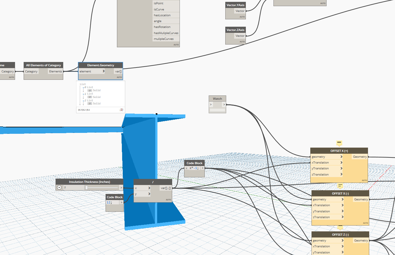
I take the geometry if the beams:

Then i thicken the surface of the beam by variable:

PROBLEM:
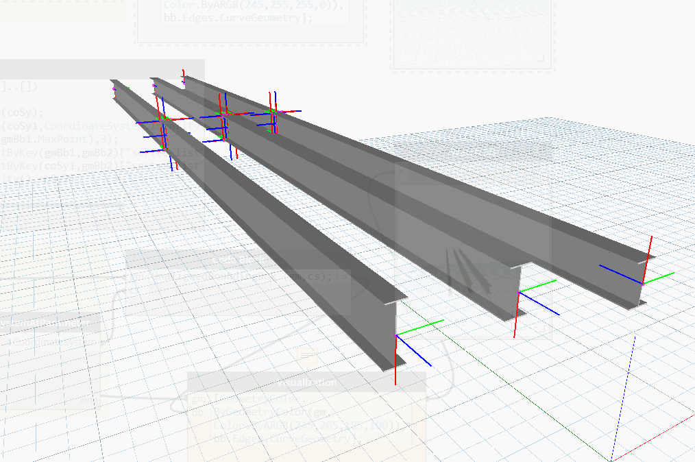
I would need the beam to fillet they corners like shown. and i dont know how to do that. Is it possible? i know it is grabing the edge of the beam and thickening it and thats why it looks like that but can i change the shape somehow to the image below?

GRAPH:

1 Like

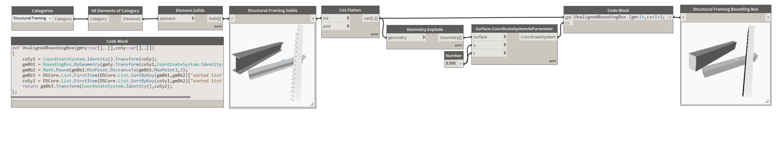
unAlignedBoundingBox.dyn (28.5 KB)
def UnalignedBoundingBox(gmty:var[]..[],coSy:var[]..[])
{
	coSy1 = CoordinateSystem.Identity().Transform(coSy);
	gmBb1 = BoundingBox.ByGeometry(gmty.Transform(coSy1,CoordinateSystem.Identity())<1>);
	gmBb2 = Math.Round(gmBb1.MinPoint.DistanceTo(gmBb1.MaxPoint),3);
	gmBb3 = DSCore.List.FirstItem(DSCore.List.SortByKey(gmBb1,gmBb2)["sorted list"]).ToCuboid();
	coSy2 = DSCore.List.FirstItem(DSCore.List.SortByKey(coSy1,gmBb2)["sorted list"]);
	return gmBb3.Transform(CoordinateSystem.Identity(),coSy2);
};
5 Likes

5 Likes
Thank you!
1 Like
@Vikram_Subbaiah I used solid thin shell and then tried to get it into revit and this is my error.
unAlignedBoundingBoxBeams.dyn (40.4 KB)

It looks like it makes the clearances in revit. but doesnt show up when i export to navis…
REVIT:

NAVIS:


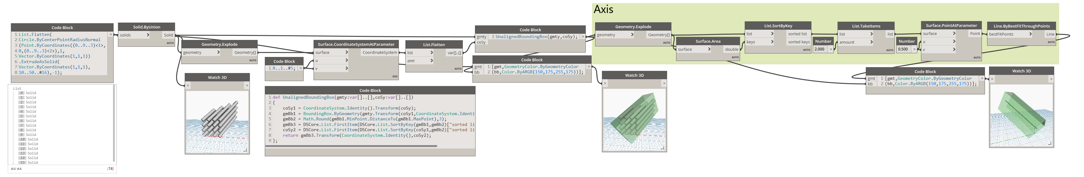
How could i get a bounding box to go around multiple geometries as a group instead of individual geometries.
Example:
I have conduit that is 4 rows in width and 4 rows in depth. I want there to be one bounding box that encompasses all of the 16 conduit.
Use Solid.ByUnion to combine those individual Solids into one Solid
2 Likes
thank you for the quick reply i will try that
1 Like
For Curved Surfaces, it might be better to get multiple points for better results.
Too many would slow down the process though.

conduits.dyn (17.9 KB)
5 Likes
@Vikram_Subbaiah Do you know how i would create a midline? from the centroid of the bounding box. Sorry i dont mean to keep asking you all these questions after you already solved the thread but youve jsut been super helpfull.
I basically want a line from the start to the end of the box but directly in the middle. almost like offseting the centriod to either side
2 Likes
Works Perfect thank you!!
@Vikram_Subbaiah im having an issue now with the sort by key… the error says input types arnt equal.

Nvm i just needed to flatten the list
1 Like
hey, Im trying to take a walls geometry and get bottom center just like your axis above but at the bottom of the wall instead. How would i do that…
You could do that by first extracting the bottom most surface of the wall and then getting it’s longer axis.
Can be done in multiple ways. Here is one possible approach …

baseAxis.dyn (22.4 KB)
1 Like