Hoping to get insight and/or a direction on how to get the code behind the Surface.Thicken function. I know it’s not part of the Revit API and it’s not accessible looking at the Dynamo code on Github. I am looking to create a similar function in C#. The closest I have gotten is extruding the surface out from a point on the surface in the surface normal direction. On a flat surface, that works okay, but I am also dealing with radiused surfaces and need the extrusion to follow the surface normal around the entire radius. Surface.Thicken works perfectly in this regard. If anyone has any thoughts, please share. Thank you in advance!
Geometry libraries are exceedingly difficult to build. Doubly so when dealing with solids instead of meshes (where everything is vector addition). Without knowing how your base classes are constructed there won’t be a functional solution.
So generally speaking you are better off sticking with the libraries you already have access to.
Towards that end, do you have a Revit surface or a Dynamo surface? If a Dynamo surface, why not use the method which should already be there? If a Revit face, why do you need to thicken it? Geometry is typically a secondary attribute of elements and most elements have a LOT of rules around how they are created.
2 Likes
@staylor the following worth trying but there are a lot to consider. because im going with tessellation so lets start off by diving into triangles.
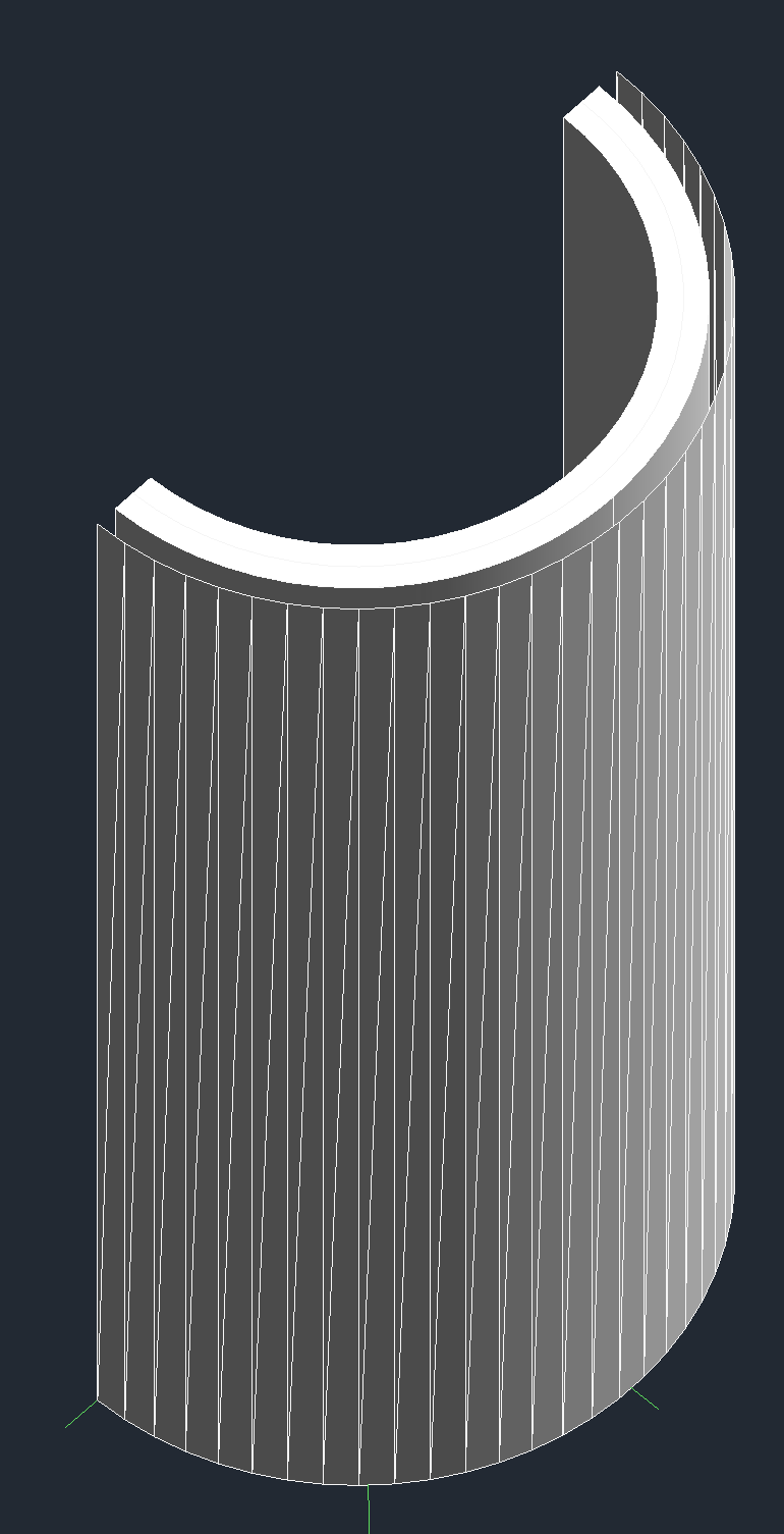
i picked two faces, a ruled face and a cylindrical one and triangulated them nicely. it is very tempting to translate vertices along face normal but that will leave gaps. better off translate them along vertex normal. at this moment, if want to “thicken” the face on both sides, u need to negate the translation vector as well. here comes the considerations:
- as u push along the normal or its negation, there’s a chance two triangles meet. im not certain if rvt tolerates this.
- u’ve only obtain two faces. so u have to seal the openings carefully. im inclined to believe one can only seal them with triangles. but perhaps mix them with quads or polygons is acceptable.
- when thickening one-side, u might need to duplicate the original face while sealing the openings. if the original is taken from an element, then its unlikely to be part of the final shape.
tbh, i often see people deal with complex geometries with some much more dedicated softwares, maya or blender for example.
i haven’t tried brep though. maybe it yields better result.
cylindrical (thickened on both sides, external face), ruled (both sides, interior)


2 Likes
This is a good example of the benefits of working with a mesh - you can use the face and vertex normals to do the offsetting. Great work @BimAmbit!
However it is likely no longer ideal for use in Revit as geometry is no longer solid. You could turn the tessellated shape into a brep, but you’ll never get curves back.
@staylor what is your use case?
1 Like
Thanks @BimAmbit I will give the mesh triangulation a try. Thanks also @jacob.small for the input.
The purpose of the function is to create a mold (negative) of the element for CNC. This would intel creating a solid geometry that encompasses the entire element with the solid of the element and one side subtracted out. Our CNC operators use other software to attain the negative, but it takes time, so trying to cut a lot of that extra work out of the equation.
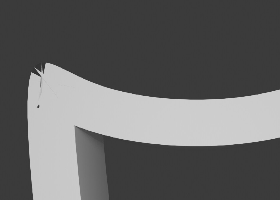
Here’s an example. First pic is of the actual element. Second is the negative with the entire back subtracted out. All other sides are left for the mold. The negative doesn’t show the brick pattern as it’s a hatch and not actual individual elements. Third pic is of a complex shape where it’s sloped, radiused with punch-outs and contoured edges. Face highlighted would be the surface to be completely subtracted out.


3 Likes
Ok - great example of when context is hugely important.
Feels like instead of thickening the surface, you’ll want to stick with the solids.
- Create a elevation view of the object to be fabricated, setting the size to be slightly larger than the element itself so that you have adequate perimeter mass for the CNC operation.
- Extract the solids from the object to be fabricated and union them into a single solid.
- Get the crop region’s curves and plane of the view.
- Get the extents of the object in the view.
- Get the min and max points of the extents and find the distance to the plane.
- Extrude the solid by the slightly less than the min and the max point distance to get a cuboid that is ‘flush’ on the max distance and slightly inboard of the min distance.
- Remove the unioned solid (step 2) from the extruded solid.
- Export the resulting solid to a format the CNC operators can use.
Note that that last step is usually the slow part - extracting all of those mesh faces can be tedius. Dynamo has a good tool for this in it’s render engine - you can explore the source code for utilizing it in the Dynamo Unfold package on GitHub. Revit also has such tools though I forget the class offhand, exporting to SAT is likely sufficient in many cases.
As always with fabrication it’s best to work closely with the people running the machine as they know the ins and outs of the machine’s limits better than we ever could.
1 Like
The object in the third pic is sloped where the top and bottom are not in the same plane. So if I am understanding your steps correctly, this would not provide a complete blockout of one side all the way to the object voided section to create the form. Below is using Dynamo for this object which gets me close. At least this would take several steps away from what the CNC operator would have to do. They would still have to trim the geometry, for their final form solid.

What do you expect the final cast look like for that form?
About 22 years ago (yes I am that old) I looked at 3D printing custom organic forms for concrete casting. In my case both sides of those walls were curving as yours are, and to achieve something which could be poured into I had to do a ‘left’ and ‘right’ side of the form, and then the formwork was filled upside down from the base which was intended to be ‘flat’ on the footing.
Assuming you need to take a similar approach of ‘two sides’, the front and back side can be split at the plane of wall, giving you one CNC machinable solid for the front form and one CNC machinable solid for the back form.
The one thing I learned as a steadfast rule was that the design of the ‘split’ in the formwork required review with the fabrication team as they are the experts around what has to happen in the context of the work.
Here’s a view from the production ticket. The bottom in form is the face of the panel (top of the view). The red outlines the CNC form/cast form. So basically rotate this view 180 degrees to get idea of what the form and cast would look like sitting on the bed. I didn’t outline the notches or block-outs.

Due to the complexity of some of the elements, I still have some issues to work out, but using the vertex normal points me in the right direction with duplicating the Surface.Thicken command. Thanks for the input @BimAmbit and @jacob.small
3 Likes