I have been trying to put together a script to automate placing valves on pipework serving Mechanical Equipment.
We have some big projects with 1000s of Mechanical Equipment instances, and so placing 1000s of valves is quite laborious and dull task. So i decided I would try to write a script to automate this task.
My workflow idea is:
Find Mechanical Equipment
Create boundary around the Equipment (with specified distance)
Find the Connected or Unconnected pipework intending to serve the Equipment
3a. Do this by finding the intersection between the Equipment boundary and pipes.
Use MEPOver fitting node to place Valve onto pipework at intersection point.
(Further checks will be needed eventually, e.g. check there is space for the valve on the pipe etc)
However, I am struggling to get my script to work. The Geometry Intersect node only outputs “Solid” instead of points, and i don’t know how to convert. Currently nothing is inserted into the model. (Note I have made the suggested change (by MEPover) to adjust the family to have both connectors as “Fitting” instead of Global.
(Also, a side point, the string leaves behind a shadow set of generic models of the pipes and equipment, which I would prefer to avoid)
Any suggestions or assistance would be greatly appreciated.
@danielU3R39 I’m curious why do you want to make a sphere around mechanical equipment?
what I’d suggest is, try making a bounding box for all mechanical equipment, then use “BoundingBox.GetElementIntersect” (BimorphNodes) to get all the pipe element intersecting.
once you have pipe elements you can get curve & center point of the pipe to place valve.
I incorporated your script, which shows a point to place the valve, but the valve is not placed. The family connectors are set to “fitting”.
In answer to you question, the reason i created a sphere, is because I need to find intersections where there aren’t actually any in the model (i.e. virtual expand the mechanical equipment). This is because at the moment, we do not always connect pipework to our mechanical equipment in our model (when using low LOD in the project)
However, i can assume that the bounding box intersect “tolerance” connector is doing something similar to this? If not, is there any way to expand a bounding box?
Thank you for your help. Below is the script with run results.
You might want to flatten the list after “List.Clean” and then Chop it to have one point in each list.
Please read the solution of this thread. It explains how MEPFitting.Bypoint works.
On the side note, are you still interested in find the the intersection point by sphere? But I’m worried that what if it finds more than one intersection point or cross contamination(nearby mechanical equipment also has intersection with a pipe,which is not associated with that)? so that’s why I suggested using Bounding Box and then find the unique elements.
Yes, you may change the size of BoundingBox.
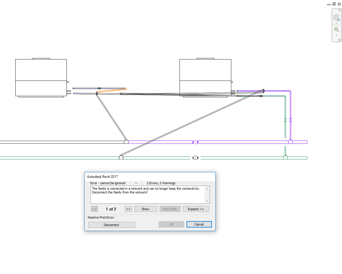
Thank you. I have followed your advice, and used the list chop, giving a list per pipe. The script worked and added the fitting, but not quite how I had hoped (see below)… The pipes have moved around, and the fitting is not connected to the pipework nor inherit the system. I have attached the valve that I am using for the test.
@jalshu Thank you very much for pointing out that silly error. Made the change, but note that I took a 2nd output from the intersect -> cleanup -> flatten. But now it works perfectly!
Sorry to ask another question. I want to try to insert different fitting types depending on the size of the pipe.
The valve family has a Family Type for each diameter size of Valve.
I am able to select the correct Family Type for each pipe, but I haven’t worked out how the node accepts multiple family types. I have tried using a flat list, as well as a chopped list (like the pipes). The chopped list gives me the following error in Revit. It looks like its inserting multiple valves.
Is there are a way for the MEPFitting node to take multiple fitting family types?
Maybe the node cannot accept multiple family type inputs… I have checked the other threads, and it looks like they use an instance parameter (instead of type parameter) in the family to change the size of the fitting.
It is possible to input a list of FamilyTypes so that shouldn’t be the problem. I think it gives the error because the python code will also try to change the size of the connectors on the family and changing the size of the family when it’s a type parameter is probably the reason for the error.
If you are somewhat comfortable with Python then you could try removing the lines that set the Connector sizes and see if that works:
@danielU3R39 If different family type is based on just size of the pipe, I feel that it would be worth investing time to make a flexible/adaptive family which will update the size of family type based on host. something similar to Autodesk’s Ball valve family from 2" to 6". So depending on host pipe’s size, It will place accurate valve size.
Thank you both. I would like to understand how a list of FamilyTypes can be input into the node. See the image below, I have used both highlighted lists with no success.
However, if as you say @T_Pover there is a way this can work, I would prefer this, as it allows more functionality with use of different valve families, as most of the valves that I have seen are built with each size as a FamilyType. And to use multiple valve types (PICV, ball valve etc) I will only have the simpler task of changing the connector from “global” to “fitting”.
Could you show the outputs that go into the MEPfitting.ByPointAndCurve node? If would also be nice if you could share the MEPfitting family for inspection.
i figure some stuff out & now it just down to getting the small issues
I have got to find a way to either rotate the hangers after your pyhton script or modify your python script to place them in the correct orientation and so far I haven’t a clue as to what I should go on as far as getting the program to know which way is up for the family it’s placing & the pipe it is placing in between.2019 - new insertion Pipe Hangers Sloping Pipe.dyn (46.4 KB)2019 - PIPE HANGER - FTG - DYNAMO COMPATIBLE.rfa (1.3 MB)
So it seems that the hangers are placed with their workplane flipped. I think you could probably figure out if a hanger has been flipped after placement and then flip them back.
I was wondering though if using the hangers in the way that you have is really what you want to do? Right now the pipes get cut up at every hanger location, to me this would not seem logical (as in: that is probably not how it will be manufactured). Wouldn’t it be better to use a hanger family that does not ‘insert’ into the pipe but just gets placed at its location (with FamilyInstanceByPoint for instance)?
It would , it would, as for now i am not doing takeoffs on pipe length. My boss wants to place embeds on the deck before concrete is poured on elevated slabs, so that we are no longer drilling in the anchors for the hangers. So I have tried to come up with the a solution that not only works right away but will also move with the pipe & pipe elevation during the BIM coordination process. The other dynamo scripts I have toyed with will place them along the curve but once the pipe moves vertically then its no longer good for BIM coordination.
I see what you mean. I’ve digged around a bit in the underlying python code and the rotation of the fittings does not seem to work exactly like it should. I’ll need some more time to pinpoint the exact cause of it.