Why are they different and do not coincide?
Could this difference cause precision problems?
Is there any thing that I can do for this?
Could this be related to “Dynamo preferences”?
My settings are:
Number Format: 0.0000
Default Geometry Scaling: Large
Dear Jacob,
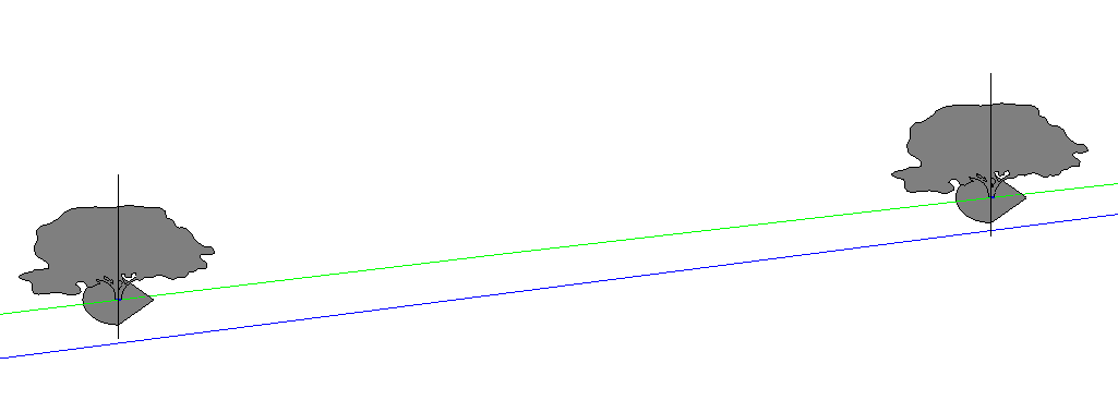
What I am trying to do is divide a portion of this CAD-located curve and place a 2 point adaptive family (5 meters length).
However, there remains a gap (~1.7 cm) between the families. So I am trying to understand why this gap occurs.
I realized that there are 2 lines. Why do we have another curve created by Dynamo?
Best regards,
What you’re doing makes sense, but we can’t see HOW you’re doing it. Post the graph and an exported image thereof using the proper method to create an image of your workspace that has been explained in the link. From there I can try to identify ‘why’.
Could be a lacing issue. Could be a calculation method. Could be geometry scaling. Could be how you’re building the curves. Could be… well anything really.
guess its a nurbscurve with hard degree, and then be inaccurate. but if that the case then you have to rebuild your cadcurve with polycurve by point maybe but guees it always be approximately
My guess is that the display graphics in Revit are different from the calculated curve which the API reads, perhaps due to large coordinates in Revit. What is the minimum and maximum point of the bounding box for the DWG instance you’re using?
Same result on medium. Should this setting be “medium” always?
I couldn’t find the minimum and maximum point of the bounding box. However, the dimensions are really big. About 4.300 meters long line and 500 meters in height. The line is coming from Civil 3D. I know that Revit has 32 km working diameter.
I wonder if this calculated curve would cause any precision problems?
It’s 22 miles if memory serves, which would be 35km. This distance applies to all geometry of the file, so what you can do is get the location point of the link instance and see where that is. If it’s more than -35km or 22 miles in the X, Y, or Z direction than you cannot rely on it’s geometry being 100% accurate in terms of display. There are things you can do to resolve this, mostly around changing the coordinate system of the DWG to the internal origin for the Revit files and keeping the Revit project within that magic 35km/22mi distance.