Is it possible to draw the shadow outline on a plan view with detail lines using dynamo?
Yes.
1 Like
haha great! I been searching but mostly just find working out the area of a shadow, not getting its outline. Can you point me in the right direction?
Have a look here ![]()
What shape/structure are you projecting?
2 Likes
At the moment its a 9 story doughnut building. Need to run a shadow study, draw the outline of it and then switch the view to another building and show the difference of the building outside the boundary height. Will hopefully be something that could be used for any building. The building inside the HIRB will just be a mass which might be easier to use for the drawn line shadow then switch to the actual building for the shadow.
As an example below, not sure if projecting the surface is the same? If it is from the correct angle 

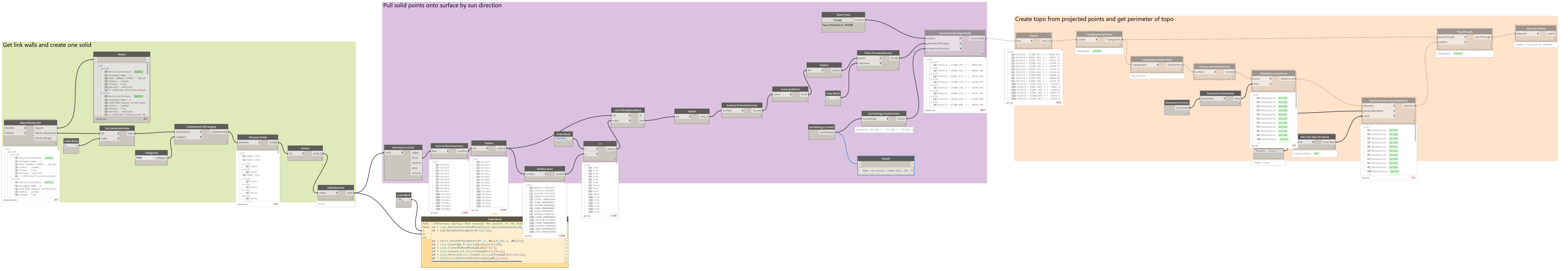
Hi @Ewan_Opie @jacob.small or anyone else. I couldn’t quite work out the link you sent me. But I came up with the below. Its a bit slow though. Any suggestions or better methods? The vector seems to project further then the Revit shadow too which I cant figure out how to fix. Thanks for any help
The line should be more where the red is

- I’d check where it is slow using tuneup
- Build a mass from the buildings and project those faces instead of the many many many many faces of the walls.
- Could be a daylight savings time bug, or that the link doesn’t share an internal origin so the elevation is different. Would need the full data set to know specifics.
1 Like
Element solids is killing it. I’m currently trying to get element.geometry from the walls then a bounding box of geometry then a cuboid from bounding box then solid union to make it similar. Element.geometry means translating the geometry though with the links. Just working on matching up the lists to translate the geometry from the emptys left in element.geometry.
I tried making like a mass shape from a few posts on the forum but couldn’t quite get it.
What tune up? A node?
I got here, fast enough. However its not very accurate with the building outline using topo method because the lines jump across if the buildings taller on one side then the other, forgot to post a pic. One building dosnt want to translate to the correct location too. A way to get the perimeter points of points would be good. Cant even seem to make multiple surfaces out of points

Manually is pretty easy, and while you could automate it for this project it might not work for the next one so I’d go manual in this case (the time to build that is likely minimal if you don’t already have the massing from another source - somehow had to sketch those walls in the first place - right?).
Information on the TuneUp view extension can be found here: TuneUp Extension: Explore your Node and Graph execution times - Dynamo BIM
Effectively it times the execution of each node on the canvas and lets you see what the slow bits are. ![]()
Thanks @jacob.small . I’m still on Dynamo 1.3  for Revit 2019. So I think tune ups no good to me for now. The current script I’ve got is fast and means I dont need to do any manual work in revit
However, do you have a method to create a surface with a group of points to draw a more accurate line of the perimeter of the points?

Hi @Thomas_Mahon do you know why this geometry isnt transforming correctly? Those 4 buildings are 1 link with attached links. The building under the surface is the same on the left linked in twice in the nested link

Hi @vanman
I had a brainwave to try and use the Revit API functions that are creating the shadow to extract the edge curves. Seems to work, and may be a lot simpler.
D2-0 Create Shadow Edge Lines.dyn (32.6 KB)


Main Coding in Python Node
## Import References
import clr
clr.AddReference('RevitAPI')
import Autodesk
from Autodesk.Revit.DB import *

clr.AddReference("RevitServices")
import RevitServices
from RevitServices.Persistence import DocumentManager
from RevitServices.Transactions import TransactionManager

clr.AddReference("RevitAPIUI")
from  Autodesk.Revit.UI import *

doc = DocumentManager.Instance.CurrentDBDocument

clr.AddReference("RevitNodes")
import Revit
clr.ImportExtensions(Revit.GeometryConversion)

clr.AddReference('ProtoGeometry')
from Autodesk.DesignScript.Geometry import *

import collections

# Flattens lists in Python
def flatten(l):
	for el in l:
		if isinstance(el, collections.Iterable) and not isinstance(el, basestring):
			for sub in flatten(el):
				yield sub
		else:
			yield el
## Converts Dynamo Planes to Revit DB Planes
def getPlane(s):
	s = UnwrapElement(s)
	origin = s.Origin.ToXyz()
	normal = XYZ.BasisZ
	plane = Autodesk.Revit.DB.Plane.CreateByNormalAndOrigin(normal,origin)
	return plane

## Input Dynamo Solid
objsolid = IN[0]

## Convert the Objects Dynamo Solid to Revit DB Solid
convertobj = objsolid.ToRevitType(TessellatedShapeBuilderTarget.Solid, TessellatedShapeBuilderFallback.Abort)

## Input Dynamo Plane
pl = getPlane(IN[1])

## Input Sunlight Vector
vec = IN[2].ToXyz()

## Create an ExtrusionAnalyser to make a Shadow
analyzer = ExtrusionAnalyzer.Create(convertobj[0],pl,vec)

## Get the Outline of the Shadow and convert to Dynamo Types
outL = analyzer.GetExtrusionBase()
eloops = outL.EdgeLoops
flatloop = flatten(eloops)
curves = []
for f in flatloop:
	curves.append(f.AsCurve().ToProtoType())

OUT = curves
5 Likes
Awesome thank you!
The post below lets me get this for getting perimeter points but the tolerance is to low.


For multiple item shadows you can patch them together and extract surface area.
So shouldnt need a Concave Hull to calculate shadow area or perimeter curves?
Does that help?

Multiple Object Code
## Import References
import clr
clr.AddReference('RevitAPI')
import Autodesk
from Autodesk.Revit.DB import *

clr.AddReference("RevitServices")
import RevitServices
from RevitServices.Persistence import DocumentManager
from RevitServices.Transactions import TransactionManager

clr.AddReference("RevitAPIUI")
from  Autodesk.Revit.UI import *

doc = DocumentManager.Instance.CurrentDBDocument

clr.AddReference("RevitNodes")
import Revit
clr.ImportExtensions(Revit.GeometryConversion)

clr.AddReference('ProtoGeometry')
from Autodesk.DesignScript.Geometry import *

import collections

# Flattens lists in Python
def flatten(l):
	for el in l:
		if isinstance(el, collections.Iterable) and not isinstance(el, basestring):
			for sub in flatten(el):
				yield sub
		else:
			yield el
## Converts Dynamo Planes to Revit DB Planes
def getPlane(s):
	s = UnwrapElement(s)
	origin = s.Origin.ToXyz()
	normal = XYZ.BasisZ
	plane = Autodesk.Revit.DB.Plane.CreateByNormalAndOrigin(normal,origin)
	return plane

## Input Dynamo Solid
objsolids = IN[0]

## Input Dynamo Plane
pl = getPlane(IN[1])

## Input Sunlight Vector
vec = IN[2].ToXyz()

result = []


for o in objsolids:
	## Convert the Objects Dynamo Solid to Revit DB Solid
	convertobj = o.ToRevitType(TessellatedShapeBuilderTarget.Solid, TessellatedShapeBuilderFallback.Abort)
	## Create an ExtrusionAnalyser to make a Shadow
	analyzer = ExtrusionAnalyzer.Create(convertobj[0],pl,vec)

	## Get the Outline of the Shadow and convert to Dynamo Types
	outL = analyzer.GetExtrusionBase()
	eloops = outL.EdgeLoops
	flatloop = flatten(eloops)
	curves = []
	for f in flatloop:
		curves.append(f.AsCurve().ToProtoType())
	result.append(curves)
OUT = result


6 Likes
Thanks Ewan. I was trying to avoid using Element.Solids as I was drawing the shadow for 4 buildings and dynamo would crash.
1 Like
Ah… there may be a way to reduce the ‘crunch’ time of extracting the element solids through other means, taking everything fully python-side perhaps . 
Or at the very least simplifying the representation of the geometry being collected enough to improve the speed (detail level options etc).
Will have another look a little later on.
1 Like
Hi @vanman
Its difficult to say just by looking at your screenshot - are those LinkElement’s walls? If so, can you try using LinkElement.Location to extract their location curves and see if they appear in the correct location as this will help to isolate the cause of the problem. It might even be something to do with the Wall Edge References maybe losing some transformation data which only the LinkElement stores, but then having said that, you Geometry.Transform node is correctly wired up to mitigate any issue with transforms which is why i cant say for sure.
2 Likes
Hey @vanman,
I’ve taken solids from quite large buildings and not had a problem (when I was doing 3d prints)… I did get some funny things when extracting Structure (there are curves in the flanges of steels for example)… Maybe it is worth trying to isolate the problem.
Hope that is helpful,
Mark
How about some image processing?
Doesn’t involve any elements or solids ![]()

shadow.dyn (2.3 MB)
//Image Processing
vwIm = rvVw.ExportAsImage(iPth);
imDm = Image.Dimensions(vwIm);
imPx = Image.Pixels(vwIm,Math.Round(imDm["width"]*accu),Math.Round(imDm["height"]*accu));
imCl = Math.Floor(imPx.Red)==127 && Math.Floor(imPx.Green)==127 && Math.Floor(imPx.Blue)==127 ? Color.ByARGB(255,127,127,127) : Color.ByARGB(255,255,255,255);
imGr = List.AllIndicesOf(imCl<1>,Color.ByARGB(255,127,127,127));

// Shadow Edge
imP1 = List.Reverse(1..List.Count(imGr));
imP2 = List.AddItemToFront(0,imGr<1>);
imP3 = List.Clean(List.RestOfItems(Point.ByCoordinates(imP2,imP1)),false);
imP4 = PolySurface.ByJoinedSurfaces(List.Flatten(Rectangle.ByWidthLength(Plane.ByOriginNormal(imP3,Vector.ZAxis()),1,1).Patch(),-1));
btLf = Point.ByCoordinates(List.MinimumItem([bsLn.Curve.StartPoint.X,bsLn.Curve.EndPoint.X]),bsLn.Curve.StartPoint.Y);
imP5 = imP4.PerimeterCurves().Scale(bsLn.Curve.Length/(Math.Round(imDm["width"]*accu)),sdLn.Curve.Length/(Math.Round(imDm["height"]*accu)),1).Translate(btLf.X,btLf.Y,0);

//Detail Curves
dtCr = DetailCurve.ByCurve(rvVw,imP5);

shadows.rvt (1.3 MB)
Haven’t attempted to exclude shadows cast within, but should be possible.
3 Likes
