Hi all, @c.poupin , @Mike.Buttery , @christian.stan
To create rebars for an orthogonal beam network where each beam spans from end to end, I need to extract the max_edge from each beam by retrieving the full, uncut solid. Then, I use the FaceNormal of the face where the max_edge lies to set the rebar distribution layout. I was able to achieve this in my previous question here.
However, and more importantly, ever since I started working with rebars in the API, I’ve consistently faced issues correctly setting the RebarHookOrientation for rebar ends. I’m still confused and don’t fully understand Revit’s rules for determining these orientations.
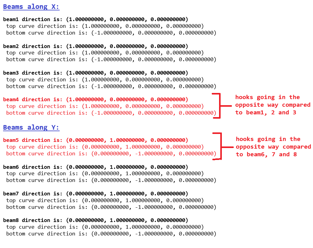
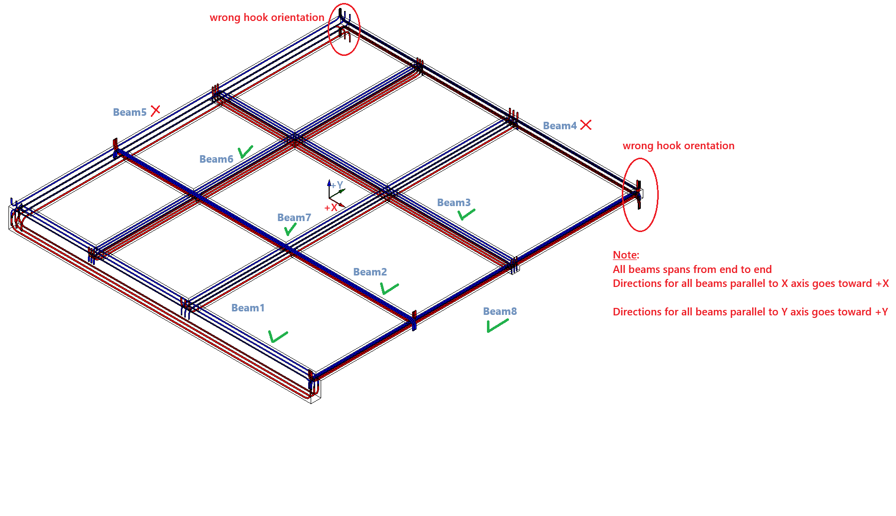
To illustrate my issue, consider the beam network example in the image below (where the first beams are parallel to the X axis and oriented toward +X, and the last four beams are parallel to the Y axis and oriented toward +Y).
When I run the code below, I get the expected hook orientations at the rebar ends for both top_rebar and btm_rebar on all beams except for beam4 and beam5, where their FaceNormal is on the opposite face compared to the corresponding beams in the same direction, I tried all possible possible orientatons, and I’m struggling to find a solution to this issue?
Here my code:
beams network
import clr
import sys
import System
from System.Collections.Generic import IList, List

clr.AddReference('ProtoGeometry')
from Autodesk.DesignScript.Geometry import *

clr.AddReference('RevitAPI')
from Autodesk.Revit.DB import *
from Autodesk.Revit.DB.Structure import *

clr.AddReference('RevitNodes')
import Revit
clr.ImportExtensions(Revit.GeometryConversion)

clr.AddReference('RevitServices')
from RevitServices.Persistence import DocumentManager
from RevitServices.Transactions import TransactionManager

doc = DocumentManager.Instance.CurrentDBDocument

# Inputs from Dynamo
top_bar_type = UnwrapElement(IN[0])
btm_bar_type = UnwrapElement(IN[1])
hook_type = UnwrapElement(IN[2])

def get_solid(beam):
    options = Options()
    options.IncludeNonVisibleObjects = False
    options.DetailLevel = ViewDetailLevel.Fine
    geoElement = beam.get_Geometry(options)
    return next((g for g in geoElement if isinstance(g, Solid) and g.Volume > 0), None)

def get_side_face_normal(solid, edge):
    for face in solid.Faces:
        if edge in [e for loop in face.EdgeLoops for e in loop]:
            normal = face.FaceNormal
            if not (normal.IsAlmostEqualTo(XYZ.BasisZ) or normal.IsAlmostEqualTo(-XYZ.BasisZ)):
                return normal
    return None

def curve_multiply_offset(curve, vector, distance, cover):
    curve = curve.CreateTransformed(Transform.CreateTranslation(XYZ(0, 0, -1).Multiply(cover)))
    vertical_offset = distance - 2 * cover

    trans = Transform.CreateTranslation(vector.Negate().Multiply(cover))
    top_curve = curve.CreateTransformed(trans)
    bottom_trans = Transform.CreateTranslation(XYZ(0, 0, -1).Multiply(vertical_offset))
    btm_curve = top_curve.CreateTransformed(bottom_trans)
    btm_curve = Line.CreateBound(btm_curve.GetEndPoint(1), btm_curve.GetEndPoint(0))
    return top_curve, btm_curve

def get_intersecting_end_beams(single_beam, all_beams, tolerance=0.001):
    loc_curve = single_beam.Location.Curve
    w = single_beam.Symbol.LookupParameter("b").AsDouble()
    h = single_beam.Symbol.LookupParameter("h").AsDouble()
    start = loc_curve.GetEndPoint(0)
    end = loc_curve.GetEndPoint(1)

    w_start = None
    w_end = None

    for beam in all_beams:
        if beam.Id == single_beam.Id:
            continue
        other_curve = beam.Location.Curve
        b = beam.Symbol.LookupParameter("b").AsDouble()

        projected_start = other_curve.Project(start)
        if projected_start and projected_start.Distance < tolerance and w_start is None:
            w_start = b / 2

        projected_end = other_curve.Project(end)
        if projected_end and projected_end.Distance < tolerance and w_end is None:
            w_end = b / 2

    return {
        "beam_width": w,
        "beam_height": h,
        "width_start": w_start,
        "width_end": w_end
    }

def get_corrected_beam_length(beam, all_beams):
    beam_curve = beam.Location.Curve
    direction = beam_curve.Direction
    beam_length = beam_curve.Length
    start = beam_curve.GetEndPoint(0)

    cut_elems = [doc.GetElement(xId) for xId in SolidSolidCutUtils.GetCuttingSolids(beam)]
    for e in cut_elems:
        JoinGeometryUtils.SwitchJoinOrder(doc, beam, e)
    doc.Regenerate()

    solid = get_solid(beam)
    if not solid:
        return None

    max_edge = max(solid.Edges, key=lambda x: x.ApproximateLength)
    max_edge_curve = max_edge.AsCurve()
    max_edge_direction = max_edge_curve.Direction
    max_edge_length = max_edge_curve.Length
    face_normal = get_side_face_normal(solid, max_edge)
    if face_normal is None:
        return None

    intersection_data = get_intersecting_end_beams(beam, all_beams)
    beam_width = intersection_data["beam_width"]
    beam_height = intersection_data["beam_height"]
    cover = 0.05 / 0.3048
    w_start = intersection_data["width_start"] or 0
    w_end = intersection_data["width_end"] or 0

    if max_edge_length > beam_length:
        if not max_edge_direction.IsAlmostEqualTo(direction):
            max_edge_curve = Line.CreateBound(max_edge_curve.GetEndPoint(1), max_edge_curve.GetEndPoint(0))
        new_start = max_edge_curve.Evaluate(cover / max_edge_length, True)
        new_end = max_edge_curve.Evaluate(1 - (cover / max_edge_length), True)
        new_line = Line.CreateBound(new_start, new_end)


    else:
        total_length = beam_length + w_start + w_end - 2 * cover
        project_point = start + face_normal.Multiply(beam_width / 2)
        new_start = project_point - direction.Multiply(w_start - cover)
        new_end = new_start + direction.Multiply(total_length)
        new_line = Line.CreateBound(new_start, new_end)


    top_curve, btm_curve = curve_multiply_offset(new_line, face_normal, beam_height, cover)
    print(direction)
    print(top_curve.Direction)
    print(btm_curve.Direction)
    return btm_curve, top_curve, face_normal

# Collect beams
all_beams = FilteredElementCollector(doc)\
    .OfCategory(BuiltInCategory.OST_StructuralFraming)\
    .WhereElementIsNotElementType()\
    .ToElements()

beams = [
    b for b in all_beams
    if b.LookupParameter("Utilisation structurelle") and
       b.LookupParameter("Utilisation structurelle").AsValueString() == "Longeron"
]

with Transaction(doc, "create rebars") as t:
    t.Start()
    curves = []
    rebars = []
    cover = 0.05 / 0.3048
    for beam in beams:
        direction = beam.Location.Curve.Direction
        width = beam.Symbol.LookupParameter("b").AsDouble()
        result = get_corrected_beam_length(beam, beams)
        if not result:
            continue
        top_curve, btm_curve, normal_vect = result

        if normal_vect.CrossProduct(direction).IsAlmostEqualTo(XYZ(0,0,-1)):
	        normT = top_curve.Direction.CrossProduct(XYZ.BasisZ).Negate()
	        normB = top_curve.Direction.CrossProduct(XYZ.BasisZ).Negate()

        else:
	        normT = top_curve.Direction.CrossProduct(XYZ.BasisZ)
	        normB = top_curve.Direction.CrossProduct(XYZ.BasisZ)
        top_curve_list = List[Curve]()
        btm_curve_list = List[Curve]()
        top_curve_list.Add(top_curve)
        btm_curve_list.Add(btm_curve)

        top_rebar = Rebar.CreateFromCurves(
            doc, RebarStyle.Standard,
            top_bar_type, hook_type, hook_type,
            beam, normT, top_curve_list,
            RebarHookOrientation.Left, RebarHookOrientation.Left,
            True, True
        )
        top_rebar.GetShapeDrivenAccessor().SetLayoutAsFixedNumber(3, width-2*cover, True, True, True)
        btm_rebar = Rebar.CreateFromCurves(
            doc, RebarStyle.Standard,
            btm_bar_type, hook_type, hook_type,
            beam, normB, btm_curve_list,
            RebarHookOrientation.Left, RebarHookOrientation.Left,
            True, True
        )
        btm_rebar.GetShapeDrivenAccessor().SetLayoutAsFixedNumber(3, width-2*cover, True, True, True)


        rebars.append([top_rebar, btm_rebar])
        curves.append([top_curve.ToProtoType(), btm_curve.ToProtoType()])
    t.Commit()

OUT = rebars
Any help would be apreciated
Thanks.