Parking and Building Massing Generative Design Graph

Hi All

I want to create a generative design graph that works out parking bay numbers and integrates building massing so the parking bays would respond to the outlines of these masses. The idea is to work out the most feasible massing dimensions and orientation while also solving for the design that gives the most parking bays.

In essence, I want to replicate the graph at the link below by @j.boonen and the grasshopper option in the following link but with a little more complexity added with massing volume positioning and orientation.

I was going to use dynamo, python and Revit’s generative design solver for this. Still, I wondered if grasshopper/Galapagos would be more suitable as this might be very geometry intensive.
I started using grasshopper and rhino, and it seems they handle geometry much more quickly. Would you say Grasshopper/Rhino is the way to go?
Will I be able to place Revit families in the project environment using grasshopper?

@jacob.small @GavinCrump @solamour

Thanks for any advice in advance.

1 Like

Rhino inside can be used to place families once you get a layout you like. I’d definitely recommend grasshopper over dynamo here due to the geometry demands these workflows place on such approaches.

Note that grasshopper has a forum as well if you go down that route.

2 Likes

Totally doable in Dynamo. In fact it is quite similar to this at the conceptual level.

One of the AU sessions I’m involved with with also cover similar concepts will also cover similar content.

The basic idea of the graph is something like the following.

  1. Generate the building footprint. How you do this is up to you; random points around the origin, number sliders for XY values, primitive, shape addition. This could be a Generative Process in and of itself. Be sure to include whatever greenery/walk/clearance you want between the building and the parking/drive lanes.
  2. Define your entry/exit point(s) via point at parameter sliders or static inputs (you might not have flexibility there).
  3. Offset your site bounds for your perimeter parking, and the drive aisle.
  4. Build a surface from the inner part.
  5. Generate a coordinate system on the surface and use it to locate the building on the site using variable UV values and a rotation value.
  6. Use a variable number slider to get an edge of the inner surface, and pull the tangent vector. Find the angle from this value to the X axis. This will define the drive aisle direction.
  7. Draw a line twice as long as the diagonal of the stie’s bounding box centered at the origin. Rotate the line by the angle found in step 6.
  8. Offset the line by the parking bay width in both the + and - direction, until the offset distance is as long as twice the diagonal of the site’s bounding box. Shift all the lines by the drive width, and drop the first line from the non-shifted list and the last from the shifted list.
  9. Define a coordinate system on the inner surface using 3 variable sliders for the U, V, and rotation. Transform both sets of the drive lines by this coordinate system.
  10. Subtract the building’s clearance geometry from the inner surface’s geometry. The remaining space is what you have for drive aisles and parking.
  11. Intersect the pairs of drive lines with the inner surface with the new opening.
  12. Transpose the drive lines so you have a set of pairs instead of two lists (could have done this before but I forgot to mention it), and loft between the two curves. These surfaces are is the parking bays. Draw an isocurve at the center of the bay (parameter 0.5), I think on the U axis (0) but it may want to be the V (1). Because we built the surface by lofting two parallel lines I am pretty sure the curve will follow the angle.
  13. Get the length of that curve, and divide it by your parking stall width. Then divide the parking stall width by the curve length. We now know the parameter spacing, and number of stalls on each line. Build a range from 0 to 1 by the spacing (leftover space but consistent stalls), or from 0 to 1 by the number of stalls (variable width stalls to fill the space). You can also ‘nudge’ a bay to get an additional bit of greenery and other stuff if desired. Drop the first and/or last parameter (depending on how your stall is laid out), and build coordinate systems for each curve.
  14. Count the coordinate systems and multiply by two; this is your parking count for interior stalls. Transform a geometry (rectangles or polycurve) to by these coordinate systems to display the stalls.
  15. Use the entry points to define circles for the width of your entry points. Use those circles to split your site boundary. Offset the split lines into the site by the stall depth, and explode any remaining polycurves to curves. Join and transpose the curves to get a pair of curves for the inside and outside of each. Sort the pairs by length so the shorter is always first. Use the first line to ensure you’re always working with the minimal dimension. From there you do the coordinate system creation a second time, using the first curve as the coordinate system. Count the coordinate system (this is the count for the perimeter parking), and transform your stall geometrty by the coordinate systems. Note that if you pick the inside curve your geometry may fall in the parking aisle, so you might need to transpose it before placement; you can split the larger list into two before you do so.

All of the above can be done with only nodes, and keeping the runtime under a handful of seconds.
This is a good outline for what the generation phase would entail. You’ll have another set of steps you outline for for evaluation, a 3rd set for addressing the technical requirements (remember node), and a outline for pushing the data back into Revit. Finally you’ll need to start catching edge cases and refinement:

  • What an edge of the parking bay doesn’t fall on the inner surface and I want to have only one spot.
  • What I don’t want perimeter parking everywhere, but only a portion?
  • What if I’m over parking the site?
  • What about handicap parking access?
  • What about EV parking/charging stations?
  • What if the building doesn’t land on the site? (Personally I evaluate this one and let GD solve it for me)
  • Etc.

It’s not a super simple task, nor should it be expected be. Building anything generative is hard, using any platform. Using them once built is easier, but even that requires changing your mindset.

7 Likes

Great summary!

I dont mean to say dynamo cant do this, but seems better to try the addin already made for rhino first and then if its suitable, rhino inside can do the revit side of things

If it doesnt do what you need, then rebuilding the logic in dynamo may be worthwhile, but seems like double the effort if the gh tools work well.

2 Likes

Some other good resources on the Dynamo side of things:

From Design Automation to Generative Design in AEC | Revit beyond BIM (Check the datasets link for a working .dyn for parking layout)

4 Likes

Thank you both for the information. Very helpful.
Yes, I’m sure Dynamo can pull this off. The issue for me was the geometry handling speed. Worth evaluating both platforms to see how they perform with a more straightforward study, I think.
Much appreciated.

1 Like

Keep in mind that how you author and handle the geometry in both platforms will impact performance. Said another way: What is a best practice in platform A could become a worst practice but gets the job done in platform B.

As a result you need to learn the specifics of each platform and test them both; this makes for a LOT of extra work. My guidance is always to ‘use the tool you know unless that tool stops working, then transition to something else’.

3 Likes

Not at my usual PC (have my travel laptop for the day) so I don’t have any of my usual reference files, or even most of my software. I do have FormIt installed which gives me access to Dynamo, but no Generative Design… but I thought this might be of use all the same as an example illustrating some of the concepts, as well as the performance speed you should be looking for (regardless of your authoring tool of choice). Built this in about a n hour between packing for a trip as well chatting/gaming with family.

Generative Site Plan

No post processing was performed there - 15fps capture in real time.
A few notes on the input controls:

  • First slider is used to generate a random site - effectively allowing flexing of the entire model as nothing is calculated without that being run first. Since each shape is random, you likely never see a duplicate form.
  • Second set of sliders defines the location and orientation of the building; I hard coded that shape in this example.
  • Third set of sliders defines the site access points. This is likely the most buggy of the group, but I didn’t want to spend too much time chasing edge cases there, as often these are something that is constrained by the site directly.
  • Fourth set is for parking layout control. This also has a few bugs around ensuring no overlap with the building clearance space, but that level of detail would want to happen after the POC is done.

A few other notes:

  • Evaluation, display configuration, and maintenance of the islands around the parking stall runs is outstanding.
  • I am also noticing a few issues with spots that you really couldn’t get a car into, so layering in something to manage curve directions is advisable.
  • This doesn’t utilize the method of selecting an edge for perpendicular rows, so turning radii would want to be accounted for in the evaluaton. I’m not sure the cocktail napkin math on that type of work, but I know it’s readily doable.
  • The building won’t always fall on site; an evaluation for building fit would be my means of accounting for this.
  • You might want an offset around the building for drive aisle.
  • Entry/exit parametrization is having some issues with trimming the PolyCurve; converting to lines earlier should resolve the issue, but that involves an extra test.
  • You’ll need to be good with design script definitions to unfurl some of this. I didn’t annotate as I went and have run out of time to put into the problem for now as I have my own generative workflows to build out for the day job, and AU prep.

Generative Site Plan.dyn (39.3 KB)

6 Likes

Thanks a ton for the examples, Jacob. I will have fun looking through it.
I’m pretty good with Design script so, not an issue.
I’ll keep you informed of any obstacles/developments.
Thanks!

2 Likes

@bayowindapo @jacob.small @GavinCrump

Thanks for the great stuff above!
The script in the orginal post is the one by @Dieter_Vermeulen (we also have it for Revit 2021 version).

For Dynamo in combination with Civil 3D, we saw a wonderful post from @marshmallow !

3 Likes

Hello. Thanks for the information.
I had a watch of the videos and it certainly helps a lot. Much appreciated.

2 Likes

Hi All

I hope you are well.
I have a question regarding the seed value in a generative design graph.
How do you know how big to make the range of a seed input so that the solver can think through every possible option in the generation process?
Should this be figured out using permutation and combination math?

https://betterexplained.com/articles/easy-permutations-and-combinations/

I covered this a bit with Alexandra Nelson from Perkins Eastman in the AU 2020 session Generative Design At Hogwarts. There is a package with the same name which has a permutation node you can utilize as well.

In a list of 5 items there are 5! or 120 possible ways to sort the list. Using a seeded shuffle it takes 473 searches to find all 120 possible orders. That’s almost 4x the amount of work. Worse yet because the results at seed 326 have no correlation to 327 or 325, generative design’s optimize feature is flying entirely blind - the optimization method might as well be tossed for REALLY BIG randomized methods from a standpoint of effective design exploration.

Meanwhile with a permutation-based solution you not only explore the space more rapidly (the 1/4 ratio expands to larger values as there is no pattern in the seeds), but there is a pattern (albeit not an easily identifiable one) in the exploration.

However the limitations to permutation-based exploration which may make it impractical. Currently the largest number which can be completely exposed by Dynamo’s Number Slider is 999,999,999,999,999 (999 trillion). Now this is a HUGE number, but it can rapidly be dwarfed by the scale of possible list permutations as you’re working in factorial space, which is indicated by the notation !. For a sense of scope, this is how that content scales up:

1! = 1
2! = 2
3! = 6
4! = 24
5! = 120
6! = 720
7! = 5040
8! = 40320
9! = 362880
10! = 3628800
11! = 39916800
12! = 479001600
13! = 6227020800
14! = 87178291200
15! = 1307674368000
16! = 20922789888000
17! = 355687428096000
18! = 6402373705728000

As you can see, by the time we hit a list 18 items deep we exceed the limit of a slider in Dynamo, which means we are missing out on at least 6,000,000,000,000,000 possible sort orders, more than 90% of the options in the set. I did build the nth permutation node in the Generative Design at Hogwarts package to allow feeding a list of slider values summing each as a 10^15th in succession (effectively performing (slider1* 10^15) + slider 2 so you get up to 30 digits). However because all sliders are mutated evenly, optimize doesn’t implement well here as the value of the first slider has more impact on the net result. If memory serves, I was effectively capped at 19 items.

There are other ways to explore larger sets, but generally speaking you should try and group items into bins, optimize the sequence of the bins, and then optimize the items in each bin, before finally merging and doing a fill or relaxation tool to ‘occupy’ the voids left over.

Hope this helps!

1 Like

Hi Jacob

Thanks for the detailed explanation.
Helps a lot!

Hi Jacob

I need to place multiple building footprints on a site surface using randomized UV values in my use case.
Using your information, I decided to cap the total number of possible building footprint generations at 17. I also divided the UV as 0…1…#17, then shuffled the UV parameter list with a seeded shuffle.
However, I get the following error shown in the image below when I change the seed input to high values. The range of the seed input accounts for the maximum permutations for a list of 17. I might be doing this incorrectly since there will be instances where the building footprints will be less than 17.

The list gets shuffled, so is this an error I should ignore?
Thank you.


ezgif.com-gif-maker

First up: I wouldn’t recommend this method for a randomized placement of buildings on a site. Instead give each building a U, V, and R number slider, allowing GD to explore the placement of each item individually. This will allow a fine degree of control (well as fine as your sliders are configured anyway) on each building. I covered a means of doing this (and defining the buildings at a Chinamo (the Chicago Area Dynamo user group) last spring, which conveniently is online here (fast foward to the 39 minute mark for the graph build). Permutation and sorted shuffle is applicable when you have limited options for where stuff might fit (ie: desks in a classroom, sequence of a pattern, etc).

This does feel a bit removed from the parking layout question though, it seems to be diverting into a new topic. If you’re trying to do an entire stie you should sit and think over how you’d do it manually first - literally write down every step of the process. Record yourself doing so by hand. Once that is done figure out how to recreate each of those steps in Dynamo.

For the permutation question: node which I was referring to above is this node from the package “Generative Design at Hogwarts”:

Randomization will always be more limited in exploration.

1 Like

Hi Jacob

Thanks again.
This graph is for building massing and parking, so still on topic, I think.
I have written down all the steps quite rigorously as well.
I assumed I would not have to set each block’s U, V and R values individually to allow the solver to test options ranging from 1 to 17.
I guess I will have to make a few scripts depending on the number of blocks/masses required.
Thank you.

Many sliders is one option.

The other is to come up with a pattern and orient the pattern on the site. Say a linear sequence of buildings along a curve.

  1. Build a list of building definitions as a list of dictionaries. I like to use xls, csv, or json to store/edit/define these.
  2. Permutate the dictionaries with the nth permutation node
  3. From each dictionary pull the width and spacing and sum them.
  4. Get the midpoint of each sum (n/2)
  5. Use math addition method on the list (sum([n[0], n[0…1], n[0…2], n[0…3]]) so you know where each item would want to be situated along the curve.
  6. Append a zero to the front of the list (you might be able to skip this depending on how you accomplished the previous step).
  7. Add the half value from step four and you’re prepped to place the buildings.
  8. Define a series of points on the site via UV parameters, and connect them with a nurbs curve. The number of points need not vary, but more points = more unique curves. Limiting your slider values can help keep things in a more expected pattern.
  9. Use the list of distances from step 7 to define coordinate systems along the nurbs curve.
  10. Pull the shape from each building definition and apply the coordinate system to each.

You can then move onto layout of the parking/whatnot.

1 Like

Hi Jacob

Thanks again for all the help.
I have successfully made a script that places five blocks using multiple nodes instead of my previous randomization attempt.
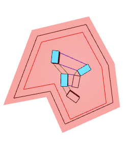
My starting point was to create a pattern for the five blocks to define their facade separations, as shown in the image below.


I then took the sums of the red and green horizontal lines connecting the corners of the masses to define output parameters (horizontal and vertical separation strength) that test/force the masses placed on the site to conform to the pattern’s separation values.

However, the generative design outputs do not seem to conform to the pattern when I constrain the output value to 100%.
I understand a generative design study is meant to reveal alternatives that designers typically will not come by themselves, which is why I have allowed this much flexibility.
Just wondering if I might be going about this incorrectly altogether in which case I will try the method in your last message.

See the graph and dependencies at the link below.
Thanks again.

The image below got me excited. Looks like the solver was starting to work towards a promising result.
image

Hey @bayowindapo I’m traveling back to the states today, and have to play catchup tomorrow; Will try and have a look on Thursday or Friday though.

Screenshots look like it’s workable, but the evaluation may need to be updated somehow.

:slight_smile:

1 Like