Hi I’m working on a multi-surface and I have a couple of questions. I’m sharing everything to see if I can get some help solving my issues.
- the node for surface subtraction is not working for me, as I think I set it properly?
- The row of hexagons with the red arrow on the image is double since there are two surfaces meeting there. How can I take off one row of hexagons from either side?
- How can I taper the hexagon pattern toward the top and bottom of the shape I have?
Corner.wire (106.8 KB)
Corner 6.dyn (58.8 KB)
Try hiding all the geometry nodes except the Surface.SubtractFrom node. (select all the nodes, right click the background, disable geometry preview, select the surface.subtractfrom node, right click it and enable the preview).
@napoleon.matheus your script only has ONE Alias surface selected. Is that really on intend?
Because you are trying to remove the red entities from the green surface here, of course this cannot work?
Make sure that you have the right inputs selected, and the right level of list access. Once we got this running, we can take care of your other questions.
Thanks,
GG
Thx Jacob. I will try your suggestions. I did try this video on you tube called Dynamo Basics 07: Trimming and Attractor Curve and for some reason still didn’t trim the circle cylinder from the organic single shape. I will try that video again with your suggestion in mind and see what happens. thx once again for the help. Also I got confuse explaining what I’m trying to achieve as I’m learning Dynamo also and doing the dynamo primer tutorials, but what I would like to do is this… Remove the inner hexagon shapes from the inside surfaces and leave the outer hexagon shapes and taper them toward the sides. Here I’m including a rough sketch, a cross section view of the side body
sorry Michael this is what I’m trying to do, like I mentioned to Jacob. All I want to do is keep the outer hexagon shapes, remove the inner hexagon shapes and taper them toward the sides like the image I include in jacob’s replied. Also the hexagons are repeating at the intersection of the two surfaces. how can I removed one or the other?
Michael now that I realize the mess I create it. I will try to redo the nodes on my end and update the both of you. Thank you so much for your time also, much appreciated and to Jacob as well
Corner 6.dyn (50.4 KB)
Hi, Gentlemen,
I update it the file. Removed the subtract node and keep the outer hexagon shapes. thanks for the help
@napoleon.matheus okay, used that script, selected the TWO Alias surfaces as input (when loading it initially, only one was selected), and added these few nodes:
Corner 7.dyn (57.9 KB)
Obviously using the same parameters for both surfaces is not useful, but in general, is this the result you are looking for?
1 Like
HI Michael, I appreciate the help but that’s not what I want to do. I don’t know if you saw my earlier post of the cross section cut, but I will share it again.
Also I do like how you combine both surfaces to do one execution I was hoping there was something like that…
Also I’m sharing an image I did in Alias but I wanted to replicate it with Dynamo so I could do different iterations on the flight
Also here I’m sharing the update it files. I removed the subtract node since I don’t think is what I’m trying to do from the images I share recently.
regards,
Napoleon
Corner 6.dyn (50.4 KB)
Corner.wire (106.8 KB)
if you load the wire file first and use Dynamo to load the Corner 6.dyn you would see this
the last image I would like to removed the inner hex shape and keeping the outer, which I tried with boolean node as shown on the file but it didnt work.
Also dynamo wouldnt bring both surfaces in at one time so I had to bring them separately and create two sets of nodes which brings me to the issue of having repeat it hex shapes at the interception of those two surfaces. How can I remove one or the other?
Regards,
NM
NM, you will need to learn how to work with lists:
In general, you should really read through the complete primer, it is very helpful to learn all needed basic concepts of Dynamo!
Here is my version of your script which shows you how to utilize the basic concepts of lists:
Corner 6-GG.dyn (56.5 KB)
To get just the outer shapes, you can work with “List.FirstItem” or “List.RestOfItems”:
Same is true for getting rid of one row:
Cheers,
GG
Hi, Michael
Thank you for the feedback on the list. I been reading primer. The old version I will read the newer version. thx for the share. I cleaned and updated the file from your comments. I don’t know if it’s a glitch on Dynamo or my error. I check and clean old the nodes and preview the ones that I need it but for some reason the hex shape size is different than the other. Would you mind verifying…
I have attached my file. Also is there a way to taper the hex shape?
Corner 7.dyn (53.3 KB)
Regards,
NM
@napoleon.matheus your hex size only looks different. You are placing them not in the same way on both of the surfaces:
Yes, there is a way to taper them, you could make their size depending on their distance to the surface edge? There are examples of attractor points in the primer online help, which should give you an idea on how to do it.
Cheers,
GG
thx Michael for the feedback. I re-did the surfaces and re-did the nodes and they all line up(I still dont know what I did wrong but everything work properly) I will try the attractor point projecting a curve or adding point by coordinates nodes which I think it will be messy since there will be too many points…will keep you posted. Thx for all the help, and I will continue reading the Dynamo primer
Hi Michael,
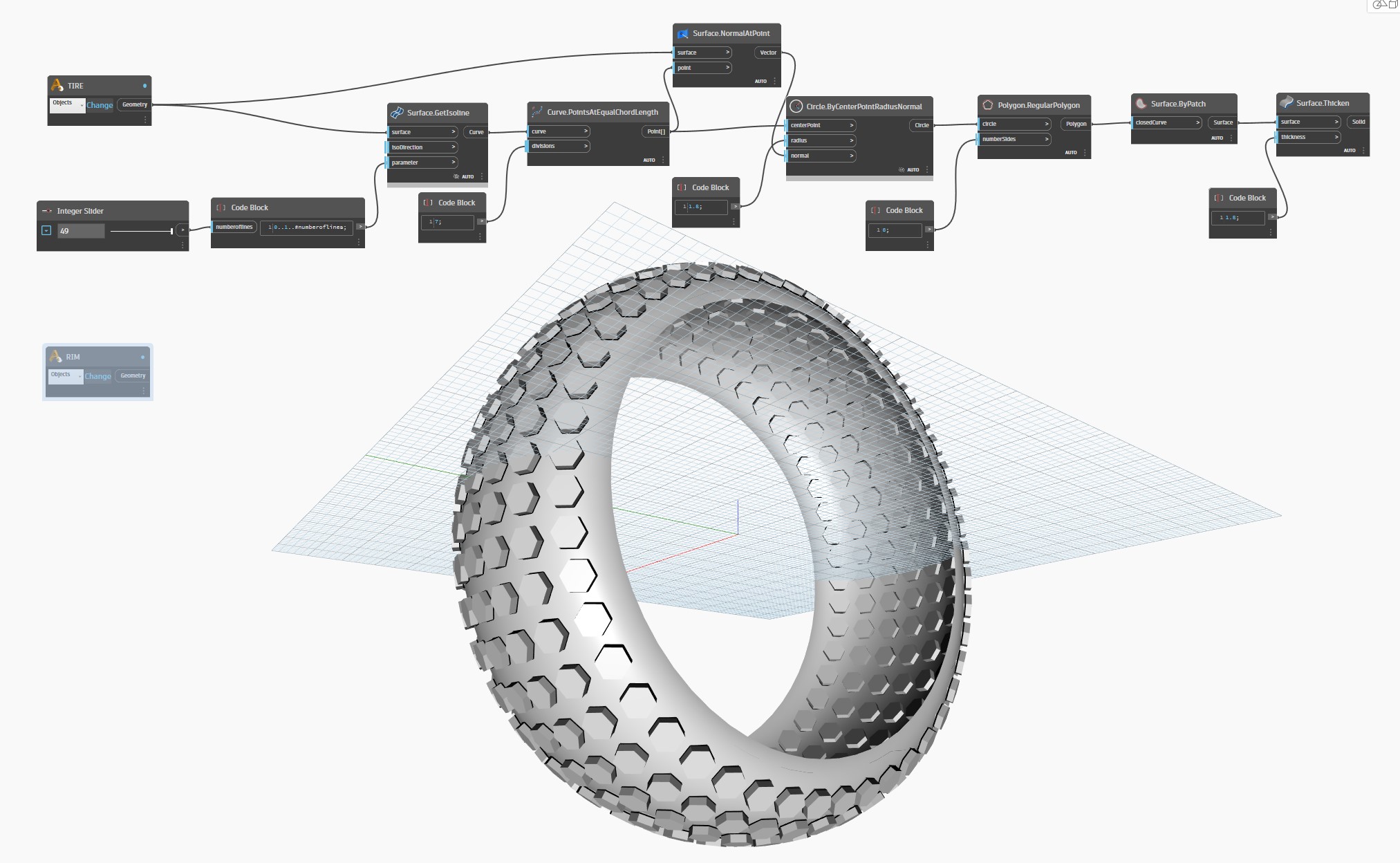
Back at it again. this time I’m trying in a simple single surface to understand what is happening. Is a tire( donut shape) I did the nodes in the proper order but for some reason the thicken node works properly but after saving and opening the same file days later the hexagon shapes move to their center point within the tire surface. I took a pic where it shows the hexagons in the proper place, but days later is moving which is weird. Is this have something to do with software glitch or video card issues. Any help will be greatly appreciated.
Wheel.wire (54.5 KB)
Wheel 3.dyn (25.4 KB)

Hi Michael,
After saving the file and closing Dynamo today, also Alias. I open Alias, load the wire file and open Dynamo and load it my dyn file and this is what happen?
BEFORE
AFTER
Regards,
NM
Hi NM,
I think you must have made a mistake. The Thicken node you are using, is always thickening into both directions, which explains your result on both sides. There is another thicken node which produces the result you are looking for:
Hope this helps,
GG
1 Like
Amigos @napoleon.matheus, @Michael-GG, have tried Extrude as Solid, it seems to work, Surface Thicken also generates a solid, the difference is that Surface.Thicken generates the whole solid only makes one side invisible, at least that’s what it makes me think when I ask for the volume, by the way what a nice script !!
1 Like
@Michael-GG, @gilberto.arechigaiba , thx for the feedback guys. Michael I tried your nodes before, the only mistake on my part I wasn’t using a neg number on the code block so I was getting the same problem. Also thx Gilberto, your approach uses less nodes which is pretty cool too. I will go with yours since is less, but I’m very happy with both options. Thx for the props on the script still much to learn…
Also like I mention to Michael in earlier messages,
I have tried attractor points from Dynamo primer, but I still don’t know how to start on a surface that is not on the grid. Since the script is done on a grid not on an actual surface?
this is a cross section of what I’m trying to do…
and this a pic from Alias of what I would like to do in Dynamo. The highlighted curve shows how I would like to taper the hexagon shapes…
Any help would be greatly appreciate it.
Regards,
NM
Is the curve given? If so, couldn’t you rotate that curve 360 degrees, to create a second, outer body, which serves at limitation? Then, from each center point of each hexagon, you could measure the distance to that outer limitation body, and extrude each hexagon according to that value?
FYI, I will be off for 2.5 weeks, traveling. Good luck with your script!