Hi All,
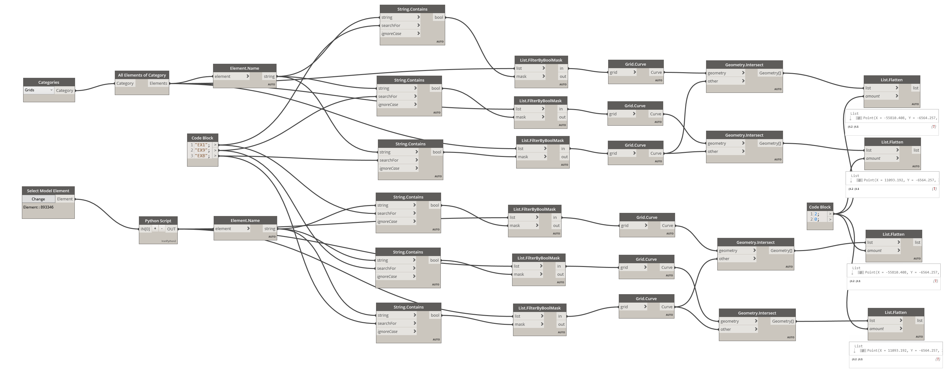
I want to move a linked revit model to align with the master model using grid intersections. I have created a script that is able extract the grid intersections from both models but I cannot find any node or method to align the two models by the grid intersections.
Please let me know if there is a way to do this.
i often see people setup shared coordinates among revit models, so once being linked, they show up at the expected position.
Yes, I know but the model was originally in IFC format, loaded in Revit and saved in RVT, so I want align this new model to master model and apply the coordinates to the new model.
I would recommend building a workflow around this logic:
- Select two primary axis and two secondary axis grids in the active document which form a box intersection, and a link instance.
- Get the grids from the link instance.
- Find the grids in the link instance as was selected in the active document.
- Extract the grid curves from the selected grids in the active document and intersect them with each each other. This will result in four points, ordered by Primary1-Secondary1; Primary1-Secondary2; Primary2-Secondary1; Primary2-Secondary2.
- Build a coordinate using the points Primary1-Secondary1 Primary1-Secondary2 and Primary2-Secondary1.
- Get the grid curves from the grids in the linked document and intersect them with each each other. This will again result in four points, ordered by Primary1-Secondary1; Primary1-Secondary2; Primary2-Secondary1; Primary2-Secondary2.
- Build a coordinate system from the points Primary1-Secondary1 Primary1-Secondary2 and Primary2-Secondary1.
- transform the link instance from it’s grid-intersection coordinates to the host model’s grid intersection coordinates.
hi
i have tried to build this script step by step
i almost completed but i am facing an issue in step no3 yes how can i determine the same grids in instance? what is the common thing which i should compare ?
I would look at the grid’s mark for most projects, as grid A in your file should be grid B in the link.
i am really apricate your support but i still have an issue the last step i transformed the instant C.S but how can i make it move to the new location inside the document am i need to use SetLocation ? i am just thinking loudly.
Got a graph and dataset to share?
Sure, I really need support here
test linked model.rvt (7.8 MB)
transform linkes coordinates.dyn (64.5 KB)
Try passing the results of Grid.Curve in the lower left group into the geometry input of the geometry transform node, then wire the grids from the lower group into the element input of an element.setlocation node, and the results of the transform node as the location input.
don’t do it.
this is a recipe for chaos and errors. you’ll move model A in model B so that it is in the right place, but B won’t be in the right place when linked into A. Then there are models C,D. E & F- you’ll be forever chasing your tail. It gets even worse if there is a rotation (true/project north) on top of the translation.
- Set up one master grid with correct shared coordinates
- use this to acquire coordinates into all other models, and copy monitor grids
if you’ve got it working properly, you be able to link rvt, dwg, ifc and other models together, and everything will be in the right place.