This is the error I am seeing.

The script tries to get the length ‘len()’ of the list of views ‘In[1]’ to iterate for all views.
This means that your input is not a list. Looks like you have connected the wrong node.
IN[0] = List of dwg file paths
IN[1] = List of Drafting views
If both lists are the same length it will import all dwgs on the views.
If for some reason you want to put all the dwgs on one view, use ‘list of repeated item’ to make a list the same length with the single view.
Should be connected something like this;

So I got it working. I can’t take credit though. An associate Jason Boehning from our training content provider Cad learning pointed out a case error between “LinkedElem” and “linkedElem”. Once that was corrected it works.
Hey Gui,
Sorry to resurrect an old post here, but I’ve been working for hours and feel like I’m so so close here. If I could get a little assistance I think I’d be there. I’m trying to take the code to import in CAD files and have the output be the linked file (either the elementID or the element itself). As you explained in your post above, the clr.Reference as I understand it acts as a function reference, so you can’t pull values out of it by itself.
I’m following the posts you linked above and feel like I’m close, but I can’t quite get it. I’m getting the boolean to fall out, but I can’t get it “True”, much less get a value from it. I’m very new to python so I’m trying to figure all this out. Any assistance or advice would be greatly appreciated.
@Konrad_K_Sobon thanks for your code,
It’s possible ton add in your python script, a out parameter with instance of dwg ?
i would like attribute a workset in a dwg file after link.
thanks for all
Best,
Hi Rémy,
One possible way is to change the output to provide Filepath.
And with a string contain and a boolean mask you will obtain the ImportInstance.


Drafting View.dyn (13.5 KB)
2 Likes
Ok thanks @Alban_de_Chasteigner Alban, I thought there would be a more direct solution.
What is the package for a node Passtrough ?
Passthrough is from Clockwork.
ImportInstance is not a commun Revit Categorie so it’s no easy to manipulate in python but more skilled users should have a better solution.
1 Like
Ok thanks, clockwork is a great package !
Hi
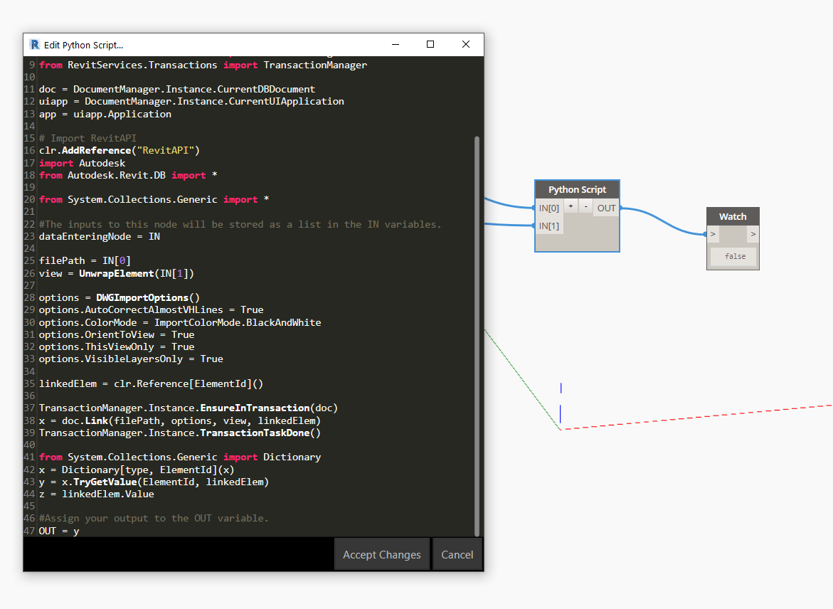
I have tried running your script but can’t work out why the visibility isn’t showing ? Do I perhaps need to redefine the options.x in the python script? I’m trying to run this in Revit 2018 so not sure if the API has much differences in these settings?

It appears in my manage links - in my VG settings though it doesn’t, I checked under the Imports in Families and it isn’t displaying any layers relating to the CAD link either ? it’s only showing the already imported not the import from the script

Once I look at my view I also can’t see the CAD link appearing in my view? but Revit is telling me it has been linked - I have already done everything I can think of in that regard of making sure the setting view range etc are correct. I tried manually linking to make sure it wasn’t the dwg file and it came in fine.
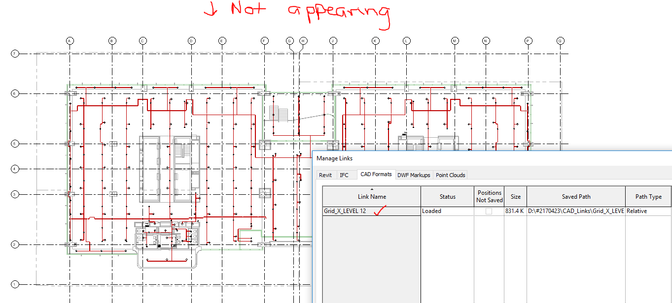
If you know why this may be happening please don’t hesitate to let me know! I’ve been investigating for hours and I haven’t been able to identify the issue - need another perception
Hi Jade,
It is not my script but that of Konrad Sobon.
I don’t see any change in the API :
http://www.revitapidocs.com/2018.1/19f4cadb-53eb-5e85-5289-022d24c076b0.htm
It may have something to do with the units or the placement
You could add the lines :
options.Unit = ImportUnit.Default
options.Placement= ImportPlacement.Centered
And change the values “Default” with your unit and “Centered” with Shared or Origin or Site.
3 Likes
Thanks for responding Alban.
I found the DWG it had come in on the sheet for some reason instead of the Level view. Will work a way around that.
Actually would you happen to know how I specify the level of placement in the script? I’m not sure of the argument arrangement.
Hopefully, folks are still watching this feed it’s been awhile since any one posted to it. I have a a script that used the python code from here to link in a DWG to a drafting view and everything works, except for the issue that the line styles are coming in as solid lines in Revit but are dashed or hidden within AutoCAD. It looks like the linking process is not bringing in the actual line pattern since all the line patterns for the linked line styles are blanks.
Here are some screenshots of the results vs AutoCAD.


Any thoughts or suggestions would be greatly appreciated.
Thank you in advanced!
1 Like
Can you share the link of solution here please, I can’t find it 
Thank you!!
Please start a new topic. This thread is 2 years old.
If you want to import DWGs, there are some existing custom nodes in packages for this purpose.
1 Like