Hello Everyone,
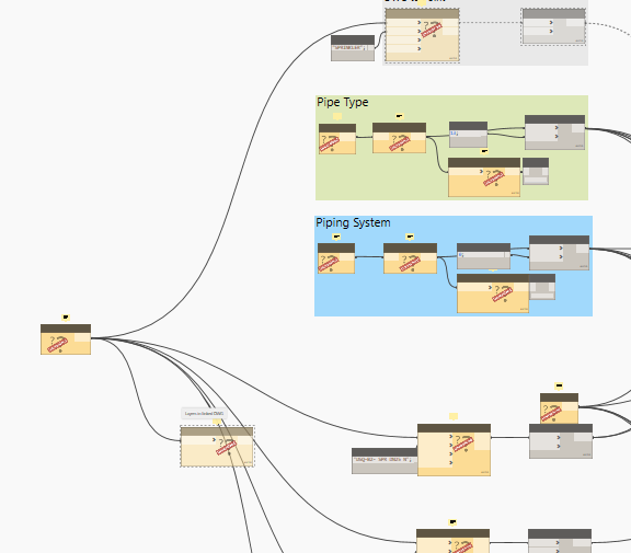
I’m trying to layout piping from Autocad to Revit based on Autocad Layer such as: Layer named DN25 will be created Pipe sized 25, DN32 will be Pipe sized 32 and so on ( I’ve attached screenshots). Well, this process is doing well (I used MEPover package) except for creating reducer and Tee for pipe which is different size (Diameter). I’m thinking about using Python to handle this work but It’s not a piece of cake for a Python beginner like me. ^^
I gazed up on each individual topic which is related to this but it seems there is no solution yet.
That’d be great to hear new idea or advice from everybody here.
Besides this approach, I have another idea that is modeling piping based on Cad text, but I think only Python can be able to solve.
DNC_DWG_To_Pipe_02.dyn (89.5 KB)
Here is autocad file.
Sorry because of confidential issue I can’t not attach Revit file here. Testing.dwg (526.5 KB)
The CAD line to revit thread might help you. This can be done without getting into python. Listing layers and applying diameter in Revit with dynamo using MEPover.
Post any progress and error you have. Still using CAD for Fire Protection? Why not just create these in Revit and forget CAD.
Thanks Wuillian, I’ve attached screenshots which is what I have done so far, there is no issue for creating pipe based on Cad layer but it is not what I expect. You can see there is no reducer, Tee,etc.
In my country, we have 4 major stages for designing MEP and stage 1 +2 will always layout on Autocad. The rest of stage will be modeled Revit, so surely we need to transform drawing from Cad to Revit.
I know it’s quite annoying but it can save a lot of time.
try gathering all the pipes after creating them in one list and feed them to the elbow and
the T node from MEPover. Currently I see one node for each pipe segments type.
if your eventually going to need a Revit a model the Autocad stages seem to be unnecessary, but I understand transition takes time.
Hello there
I want to do the same thing. I saw a video that sprınkler the dwg from excel to revite. my main purpose is to transfer these pipes to revision. I tried adding you, but I think dyn1.3 couldn’t open it, so I upgraded it again. how can i run dynamo
Thank you Wuillian, the T node only for branches pipe and main pipe connect, so I think there is no way for using it in my situation.
Anyway, Most of company in my country there are using 1 layer for all pipe, and the way they identify them is using Text notes, it means if I wanna layout pipe from Cad to Revit automatically, I have to think another solution.
There are 02 options for you. One is download dynamo 2.0 and open my script.
Second is mimic my node on screenshot. But for you information, my script only draw pipe based on layer, it depends on your piping layer.
I downloaded dynamo 2.0 and opened your scprit.
but which nodes are composed of parameters. It is not complete because it is empty.
My English is weak
I’m using dynamo version which is attached below:
Can you take a screenshot about your issue here?
normally 1.3
2.1e in this way

The problem is lacking of packages. 
You can download these package: MEPover, Rythym, String, Data Shape,etc. The only way you can know which package is passing node name on internet and take a look. or asking the people who write it. But for some urgent situation I prefer searching on internet.
Cheers.
thank you so much.
When the version was upgraded, packages were going away. I couldn’t find which packages to download. helped. I will try.