I am trying to use Dynamo to add tags to MEP ductwork. I have done this for several tags with various success. The one that I don’t know how to do is to add tag to show FB/BU/BD (Flat Bottom, Bottom Up, and Bottom-Down). I can see that there are settings available in Manage → MEP Settings → Mechanical Settings → Duct Settings. In that page for Duct Settings, I can see these:
Setting “Flat On Bottom” has the value “FB”.
Setting “Set Up From Bottom” has the value “BU”.
Setting “Set Down From Bottom” Has the value “BD”.
Seem like I should be able to take advantage of those pre-set settings. But I just don’t know how to get those values to show up in a tag reliably.
I am guessing that I need to use the parameter “SU/SD from Bottom” in a custom tag, and then ask my Dynamo script to add the custom tag to a duct (in my case the duct is Transition duct). But sometimes it works, sometimes doesn’t.
For example, the tag in a Bottom-Up duct correctly shows BU1 3/4" to indicate that it is bottom-up by 1-3/4". That is correct.
On the other hand, a flat bottom duct shows FBCL= instead of FB. CL= means Center-Line. I don’t know why this shows up.
Another example is a flat bottom duct shows FBBU1 3/4" instead of just FB. This is very odd. I don’t know where the BU1 3/4" comes from. The duct is flat-bottom, and it is not bottom-up.
Does this have something to do with the fact that I am using Revit 2021? I see that there is a technical article in Autodesk with Incident ID 184759 that said, “Offset tag SU/SD top parameter reporting incorrectly in Revit”. Seem like the problem “may” have been fixed in Revit 2022 and above – that is if I understand this correctly. Unfortunately, the company that I work for uses Revit 2021. Now what should I do?
I can use my Dynamo script to tell which transition duct is flat bottom, which one is bottom-up, and which one is bottom-down, and I can assign my custom tag to the duct. But I don’t know how to ask the custom tag to show something like FB, BU1 3/4", or BD2".
It sounds like you need to split this into a “Revit problem” and a “Dynamo problem”. You need to determine how and why Revit is acting a certain way before you can automate it. Unfortunately, this is not the correct place for Revit questions. You’ll have to use the Revit forums for that. Once you have everything sorted out on the Revit side and you can get your logic working correctly in Revit, then we can discuss how to automate that process in Dynamo.
I understand the idea of grouping all the relevant topics in one place.
Seem like the most logical way to get the correct tag to show up is to use “SU/SD from Bottom” parameter. But that one doesn’t seem to work in Revit 2021, and I cannot upgrade to Revit 2022. This means I am stuck. And I need to find a way out.
Because I am a programmer, and I can write a program to fix many things. Therefore, my natural inclination is to use Dynamo script to fix the problem. That may or may not be the right way to fix this problem. And hopefully I will find out.
This is the Python code to get the list of center-points:
# Import section
# --------------

# Load the Python Standard and DesignScript Libraries.
import sys
import clr
clr.AddReference('ProtoGeometry')
from Autodesk.DesignScript.Geometry import *

# Import these for XYZ.ToPoint() conversion.
clr.AddReference("RevitNodes")
import Revit
clr.ImportExtensions(Revit.GeometryConversion)

##########################
# Cannot import this. Otherwise, we cannot construct Point or Line because
# of namespace conflict (Point and Line class are defined in both
# ProtoGeometry and RevitAPI libraries)
##########################
## Import Revit API
#clr.AddReference("RevitAPI")
#from Autodesk.Revit.DB import *
##########################

# Import these to get access to DocumentManager.
clr.AddReference("RevitServices")
from RevitServices.Persistence import DocumentManager

# Define Inputs
# -------------

lstFabPcs       = IN[0]  # It is a list of Fabrication MEP pieces.
sLookForBtmType = IN[1]  # It can be "BU", "BD", or "FB".

# Process
# -------

# Determine the center-point of each duct in the list if the bottom
# of the duct is the specified type, and save the result to a list.

lstCenterPts = []

doc = DocumentManager.Instance.CurrentDBDocument

for pc in lstFabPcs:
   # Get commonly used info about the piece.
   pcUnwrapped = UnwrapElement( pc )   # Get access to more properties.

   # Ignore any piece that is not transition duct because all other piece
   # type are always flat bottom, and we don't need to worry about if it is
   # bottom-up/bottom-down/flat-bottom.

   bIsPcAlwaysFlatBottom = True

   idType = pcUnwrapped.GetTypeId()
   oElementType = doc.GetElement( idType )
   sPcFamilyName = oElementType.FamilyName
   if ( sPcFamilyName == "Transition" ):
      bIsPcAlwaysFlatBottom = False

   # Determine if the duct whose bottom is the type that we are looking for.
   if ( not bIsPcAlwaysFlatBottom ):
      # Retrieve the "Offset-Depth" of the duct.

      nOffsetDepth = 0

      lstDimensions = pcUnwrapped.GetDimensions()
      for dim in lstDimensions:
         if ( dim.Name == "Offset-Depth" ):
            nOffsetDepth = pcUnwrapped.GetDimensionValue( dim )
            break

      # Determine if we should output the center-point of the piece to the list.

      bShouldOutputCenterPt = False

      if   ( sLookForBtmType == "BU" and nOffsetDepth > 0 ):
           bShouldOutputCenterPt = True
      elif ( sLookForBtmType == "BD" and nOffsetDepth < 0 ):
           bShouldOutputCenterPt = True
      elif ( sLookForBtmType == "FB" and nOffsetDepth <= 0.125 and nOffsetDepth >= -0.125 ):
           # Offset within +/- 1/8" is considered as zero.  This is to avoid any
           # rounding error.
           bShouldOutputCenterPt = True

      if ( bShouldOutputCenterPt ):
         bConnEnterFound = False                            # Initialize the info of
         ptEnter         = Point.ByCoordinates( 0, 0, 0 )   #   Connector-Enter.

         bConnLeaveFound = False                            # Initialize the info of
         ptLeave         = Point.ByCoordinates( 0, 0, 0 )   #   Connector-Leave.

         for cn in pcUnwrapped.ConnectorManager.Connectors:
            if   ( cn.Id == 0 ):
                 bConnEnterFound = True
                 ptEnter         = cn.Origin.ToPoint()   # Convert from XYZ data type to Point.
            elif ( cn.Id == 1 ):
                 bConnLeaveFound = True
                 ptLeave         = cn.Origin.ToPoint()   # Convert from XYZ data type to Point.

         # Calculate the center point of an imagined line between the centers
         # of two connectors.
         if ( bConnLeaveFound and bConnLeaveFound ):
            ptCenter = Point.ByCoordinates( ( ptEnter.X + ptLeave.X ) / 2,
                                            ( ptEnter.Y + ptLeave.Y ) / 2,
                                            ( ptEnter.Z + ptLeave.Z ) / 2 )
            lstCenterPts.append( ptCenter )

# Output the list of center-points of the pieces whose bottom
# are the type that we are looking for.
# -----------------------------------------------------------
OUT = lstCenterPts
Note: The Home Workspace is designed to use 3 different Custom Tags because I don’t know if I need to use 3 or just one Custom Tags. In this example, I only need one Custom Tag to illustrate the problem.
The following are the tags placed on transition duct:
From the Autodesk Help descriptions: The value is determined by the face that is closest to the view plane. The flow is assumed to be from the primary connector to the secondary connector of the part.
This is just default Revit behavior so the issue is likely due to either of the above statements. There’s not really anything you can do to override these values. You’d have to check the families and the placement/orientation of the instances to confirm they match the requirements as expected.
Thanks for trying to help. I believe what I get from the definition of “Flat on Bottom” is that I need to make sure the bottom face of the transition duct is indeed pointing down toward the view plane. Sometime the transition duct may have been rotated and the side may be pointing downward. When this happens, the “Flat on Bottom” will be based on the side of the transition duct that is facing downward.
Unfortunately, I have checked the transition duct in question, and they are all upright – meaning that their bottom part are facing downward toward the floor plane.
I have done a bit more test, and I have installed Revit 2022 in my computer. Based on the test, both Revit 2021 and 2022 exhibit the same problem – meaning that “SU/SD from Bottom” show wrong info (CL=). This means the problem has nothing to do with which version of Revit I use. The problem may have to do with a certain settings in Revit.
As of now, the best course of action is to ask around in Revit forum to see how to fix this problem in Revit – just like what you have said. Thanks.
If this cannot be fixed in Revit, I will come back here to ask again to see if I can use Dynamo to force Revit to show “FB” in the tag and nothing else without using “SU/SD from Bottom”.
By the way, further testing shows that “SU/SD from Bottom” works fine with both BU and BD. It just doesn’t work with flat bottom.
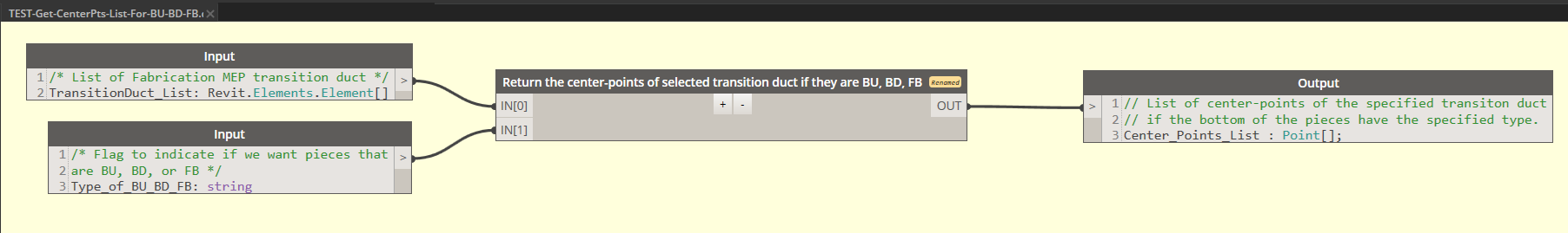
I figure out why one of the transition duct that is flat bottom gets a tag BU1 3/4. The Dynamo script has a bug. It passes the entire list of transition duct to Create Annotation Tag block that is for assign FB tag. The list should have only included transition duct that are FB. The links with the red-cross shown below are wrong and should be fixed:
I still don’t know why flat bottom transition duct that have offset-left or offset-right are shown with CL= that should only be for Center-Line. As mentioned previously, I will ask around in Revit for MEP forum.
I find out that my understanding of Centerline is different from Revit. Revit thinks that a duct is Centerline as long as the depths in both ends of the duct are the same regardless if the duct has an offset in its width. That’s why Revit places a CL= in the duct because the depths of both ends of the duct that I use for testing are the same.
Unfortunately, that is not what I want to see. I will have to figure out something. The solution may or may not need Dynamo. I will see…