Hello! I managed to create a script that can array columns along a line. But how do you create a script that works for beams as well? To create a beam you first have to determine it’s length which means that you have to type in it’s length in the script before the script tries to array it. I can’t figure out how to do that part of the script together with the part that arrays it. The green part that determines its length only work if the beam already exists. Which it doesn’t. And I don’t know how to combine it with the rest of the script.


Look into the StructuralFraming.BeamByCurve node.


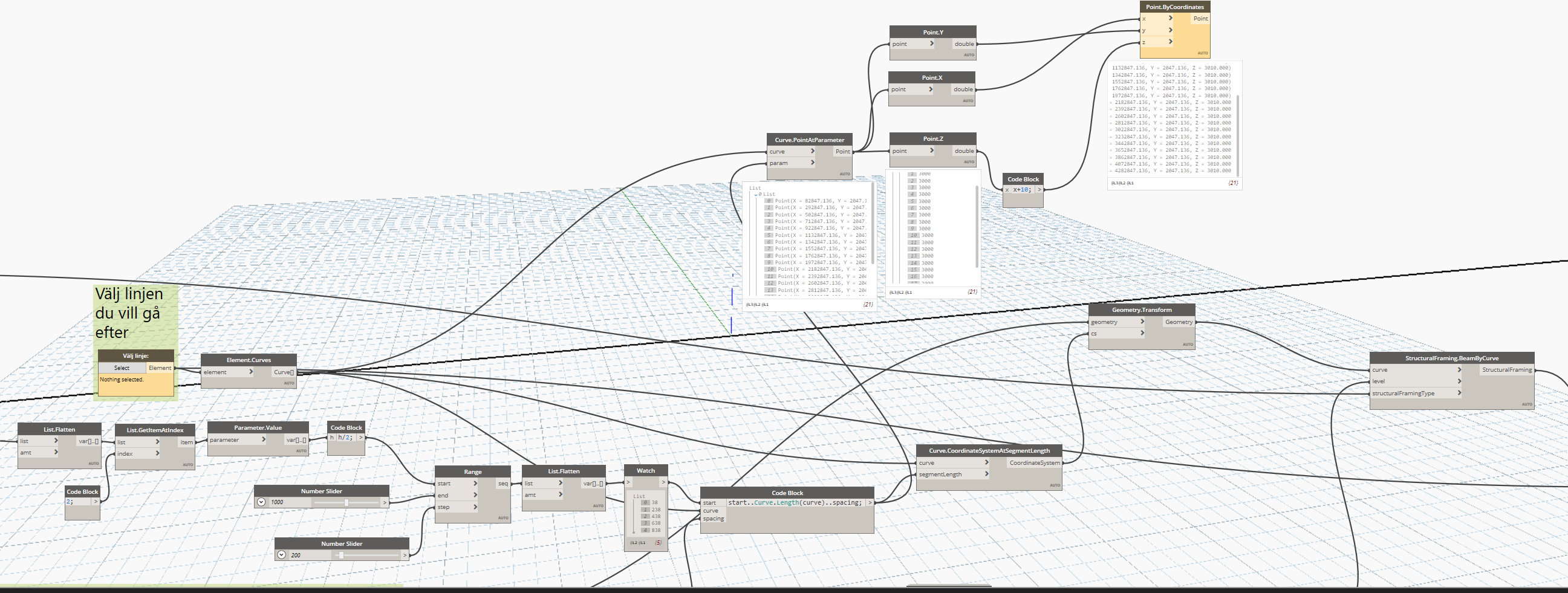
Quite possible, and fairly straight forward:
- Get the line you want to use as your array
- Get a series of coordinate systems dispersed along the array line
- Draw the line which you want to be your ‘beam location’ as if the global origin was your beam’s center
- Apply the array of coordinate systems to the beam location line.
- (not shown) StructuralFraming.BeamByCurve to make the actual framing.

That helped me a lot! Thank you so much!
I’m still having problems though. I tried implementing your nodes/script into my script and the beams end up in the completely wrong way. They end up standing up somehow.


tt beam.dyn (86.9 KB)
Review your coordinate system’s local axises and compare to the global axises.
I don’t understand how that works. Could you please explain? I would be forever grateful.
Can you post a screenshot showing the coordinate systems along the line you’re arraying on? Need a graphic representation. ![]()
Nevemind! I was wrong. The script from my last screenshot actaully works perfectly fine!
I interpreted the end result totally wrong because I had an extremely low value set for the relative location line  Thank you so much for your help!
Hello Again!
Do you know if I can somehow be able to create a slop for the array? I would like to have an input where I can just type in the angle for the slope (e.g. 45 degrees). I guess that I somehow need to control the points at the Z-axis if I’m not misstaken? I just don’t have a clue how.


gg.dyn (54.7 KB)
I’m not sure if I should start a new topic about this. I’m very grateful for all help I can get
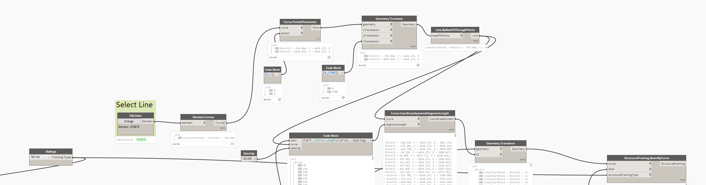
Try getting the array curve’s endpoints with a curve.pointatparameter node, and then moving them with differeing values - one the desired height and one 0 units on the Z axis with a geometry.translate node. Then make a new curve, and use that to get your coordinate systems.
I don’t understand how. I’m a beginner with Dynamo so this is very extremely hard for me to grasp.
I tried getting the curves endpoint like you said. Don’t I need to set a new value to the height for the coordinates in the Z-axis? To be honest, I have no clue what I’m doing even after hours of tryng to understand 


This is a lacing issue. You’re on Auto lacing, which means if you feed lists into all inputs it will default to shortest lacing - index will match to index until one of the lists is out of items. This is what you’ve got above as both your curve and the parameters are a list. However with Auto lacing if one of the inputs is a single item instead of a list then longest lacing is applied, where the single item is matched with every one of the items in the other list. I fed a single curve, and therefore got that result.
Since you have some opitons:
- Pull the curve out of the list with a List.ItemAtIndex node, List.FirstItemNode, or list indexing in Design Script (
listInput[0];) - Modify the lacing to be cross product (every item in list one is mixed with every item in list two)
- Add a list level input to force the curve to be treated as a singleton (@L1)
Personally in this instance I’d go with the list level solution as it’s more robust and can be used to maintain the nested structure over time (should someday you want a nested list of curves).
More info on lacing is here: 05 - Understanding lacing in Dynamo (Dec 2020) - YouTube, and I discuss list levels in the next session. though the full video series may be worth reviewing.
Ahhhhhaaaaaa! Thank you explaining it for me. I always thought it was difficult to understand but not anymore
I went with the second option where I modified the lacing to be cross product. And it works!! Wow this gave me so many more ideas!
I recently discovered a big problem though and I don’t know what causes it. Whenever the second value for zTranslation crosses 1200-ish, it arrays in a weird way where it doesn’t array the whole way to the endpoint

If that view is a Revit view, check to make sure that the beam isn’t just above (or below) the view’s range, causing it to not be displayed. if it’s a Dynamo view, can you upload your DYN and .RVT file so I can have a look?
You are right. It was just the view range. Thank God 
I just discovered another problem and that is whenever I set an angle to the array i.e. give zTranslation a value over zero, the spacing becomes incorrect. In the example below, I give the spacing a value of 100, and it somehow becomes 95 instead in the Cuve.CoordinateSystemAtSegmentLength node.
The higher up you go, the smaller the spacing becomes.


hh.dyn (261.1 KB)
I don’t think that’s it’s an issue with the lacing this time because it seems correct to me (I could be wrong!). I don’t understand why this is happening 
Is that a plan view you are drawing the dimension in, while looking at an object drawn on an angle?