Hello there!
I am new to Dynamo and atm am trying to learn how to generate geometry based on mathematical formulas. As reference I am using a book called “Morphing: A Guide to Mathematical Transformations for Architects and Designers” and in it different shapes and curves are explained through math formulas and functions.
My question is how do i implement them in Dynamo and Revit. I have tried the Math section (where I believe my answer lies) but to no avail. No doubt it’s due to my lack of knowledge of the program and syntax, but I would really appreciate some help.
I am attaching a random page from the book so you can see what exactly the format is.
Thanks in advance !
EDIT:
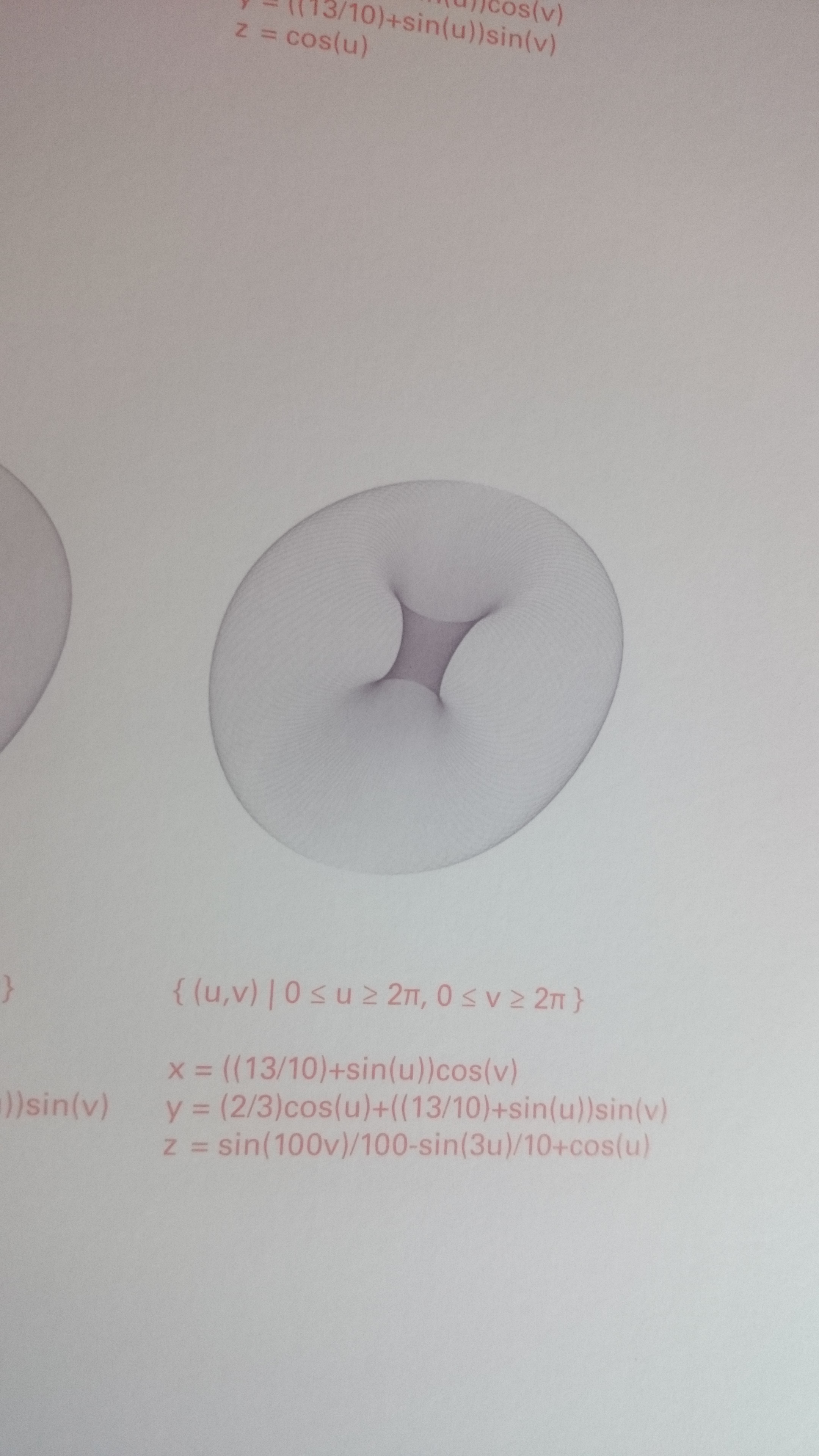
I realized the photo is of too poor a quality to read the fine print so these are the lines under the last scheme (I assume the others have a similar method)
{ (u,v) | 0<=u>=2pi, 0<=v>=pi }
@Yna_Db thanks for the quick reply.
I based my efforts on this particular section of the primer http://dynamoprimer.com/en/04_The-Building-Blocks-of-Programs/4-2_math.html
although I understood the basic idea behind it, but this completely eludes me "{ (u,v) | 0<=u>=2pi, 0<=v>=pi }".
I will keep looking through the Primer examples you linked and will definitely check out that package
Where does this come from? I don’t see it on the page you mentioned.
It looks that u and v values will be comprised between 0 and 2pi, and 0 and pi, but I would rather have used <= only for that, I would be curious to see that in its context
Ah, OK, I see. I have to leave now but quickly, as I said, I would rather try this way:
0<=u<=2pi, 0<=v<=pi
because as it’s written, it looks like a contradiction.
I am sure someone else will help with it…
I’m not sure if Dynamo’s geometry kernel can handle self-intersecting surfaces like the ones in the pictures. The x,y, z formulas describe the basic shape. You then have to apply additional shearing and reversing of the individual “layers” of points to get the end result:
It is exactly that… I thought something looked funny but it was really late and I dismissed it lol
Will give it a fresh go today with your suggestion
@Dimitar_Venkov
Thank you so much! I will look at your code more carefuly when i open up dynamo and will try to figure out the other shapes in a similar manner. only question i have is about the last two lines of the first code block ( the second more than the first actually) but i think they will clear up once i try it your way and see what they do
u = 0..360..#10;
v = 0..180..#10;

x = ((13/10) + Math.Sin(u))*Math.Cos(v);
y = ((2/3)*Math.Cos(u))+((13/10)+Math.Sin(u))*Math.Sin(v);
z = Math.Sin(100*v)/100-Math.Sin(3*u)/10+Math.Cos(u);

p = Point.ByCoordinates(x,y,z);
c = NurbsCurve.ByPoints(p);

d = c.Rotate(Point.Origin(),Vector.ByCoordinates(0,0,1),0..360..2);
e = List.DropItems(List.Sublists(d,0..1,1),-1);

f = Surface.ByLoft(e);
g = Solid.ByJoinedSurfaces(f);