Was a bit bored tonight and wanted to play around. Obviously you’ll need to update to manage control of the tunnel’s profile (the elevation as it travels the alignment), but this should allow generating a parametrically controlled alignment. Two graphs to do the work as I didn’t want to fight document switching as that gets to a much higher degree of difficulty and I just wanted to do something simple and fun with the time I had.
Graph 1 is the “Make Profile Family” graph:
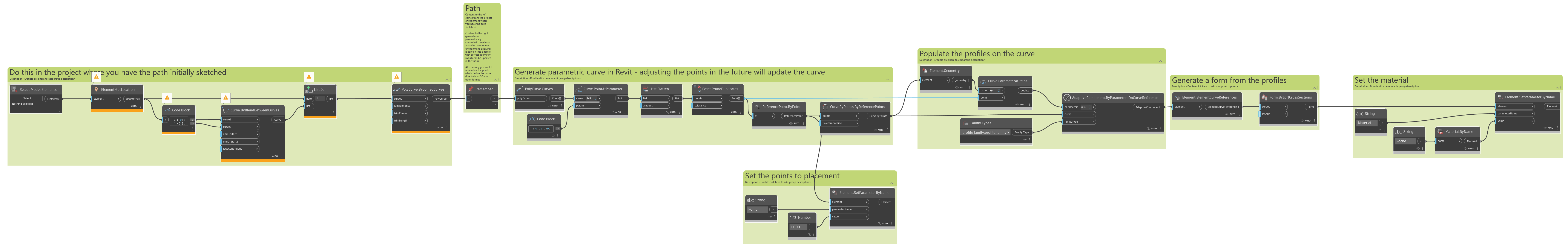
Graph 2 is the “Make Tunnel Family” graph:
And the results are pretty smooth looking:
How to is broken down into steps below.
Step 1 is to extract the geometry of the tunnel section - this is done by select edges in your project environment where they were sketched before, but you could use other methods as well. The geometry is wired into a Remember node, and we move over to an adaptive component environment. This happens from the leftmost node to the Remember node of the “Make Profile Family” graph.
Step 2 is to transform the extracted geometry to the origin, reorient it for use along a reference curve, generate model curves, and add a single adaptive point to control placement. Note that when you switch documents you will have to close Dynamo for Revit. This happens from the remember node to the rightmost node of the Make Profile Family" graph.
Step 4 is to extract the geometry of your alignment - this is done back in the project environment where they were sketched before, but you could use other methods as well. This geometry is wired into a Data.Remember node. This happens from the leftmost node to the remember node of the “Make Tunnel Family” graph.
Step 5 is to start another new adaptive component family, and load the profile family into it. No automation here - it’ll be as fast to hit ‘new family’ yourself and select your template as it would be to run an automation tool which then asks for your template.
Step 6 is to generate the tunnel family by generating a series of points along the alignment curves, generating a curve by points, placing instances of the tunnel section family at each point on the curve, and finally generating a form by all of the tunnel sections. This is done from the remember node to the right most node of the “Make Tunnel Family” graph.