Hi All
Trust you’re well.
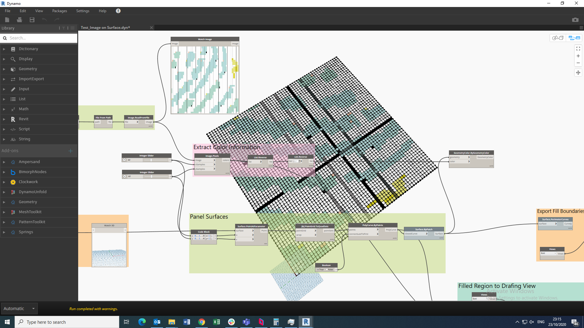
I’ve got surfaces in dynamo that I’ve mapped colors onto with an image. Is there a way to export these surfaces / solids with their colors to a Revit family?
I imagine this would be done by overriding the material shading or surface patterns. Which also means a list of materials will have to be created that represent the colors of my input image.
Please see dyn file and images attached.
Thanks for your help in advance. @jacob.small
Test_Image on Surface.dyn (61.6 KB)
1 Like
The genius loci package from @Alban_de_Chasteigner has some great nodes to make materials. Search the forum for examples on how to use them as the API requirements are complex, which means the nodes can feel that way at first. Alban has done an amazing job showing people how to leverage them though - that package is truest in my ‘must have’ package listing now.
As far as how… I would group your surfaces but material, pull the corner points, place quad surfaces as adaptive components, and set the material parameters accordingly.
Biggest benefit there will be scheduling, counting, and continued flexibility for the design team. Moving the geometry of each as a family is wasteful from a file size standpoint.
Give it a shot and see where you get. 
2 Likes
Many thanks. I’ll give it a go!
Hi All
Thanks again for all the help.
Not sure if I should create a new topic for this since it is pretty related to my end goal.
Here goes. I’ve successfully made my 33 x 300mm tile pattern grid and mapped colors onto one of my intended surfaces using an image.
The issue I’m having now is that the tile pattern I’ve got also needs black, yellow and brown quarter tiles mapped into the grid where there are green tiles. This obviously presents more complexity because the quarter tiles deviate from the 33 x 300mm grid pattern. Is there a way of doing this using dynamo or is this too complex? The quarter tiles probably have to placed using a script that randomizes their placements.
Please see dyn file and images attached. @jacob.small @Vikram_Subbaiah
Let me know if anything is unclear. Thanks in advance.Temple Tiling Pattern Script.dyn (131.5 KB)
First up, make sure you have Generative Design or Refinery installed, and have downloaded the Refinery Toolkit package as well. After you have created the group of green tiles as geometry objects:
-
Ude a data.Remember node on the green tile list if you would like to use Refinery or Generative Design to bulk explore the randomization.
-
Use a List.SeededShuffle from the refinery toolkit to shuffle the list of tiles so they are no longer in a usable order. Using the seeded variety as if you don’t like the results you can ‘redo’ it here and you can also ‘go back’ and get the same results should you decide ‘actually I guess that was good enough.’ Make the seed value a number slider, name it seed, and mark it as an input.
-
Take the desired number of tiles to be recolored out of the list with a List.TakeItems node. Similarly remove the tiles from the list of green tiles with a List.DropItems node.
-
Find the geometry of the tiles to recolor to get the outside surface of the solid (filter based on normals being close to the original surface’s normal or based on areas).
-
Build a list of [null, 0.25, 0.5, 0.75] and use a List.OfRepeatedItems to get a number of lists that is equal to the number of tiles you want to recolor.
-
Build a range from 1 to the number of tiles to be recolored, and use that with a List.ShiftIndex node to shift each sublist by it’s own index - first will start at 0.25, next at 0.5, next at 0.75, next at null, next at 0.25 and so on. Then take the first two items from each list.
-
With the paired list of values, use a List.Clean to remove any nulls - you will now have a parameter value set to use to build your randomized cuts on your surface.
-
Draw isocurves on the surface from step 3, using the parameter sets from step 6. Extrude these by the inverted normal of the surface with a distance equal to 3x your tile thickness. Then move them by 1x the tile thickness along the normal, and combine each sublist into a Polysurface.
-
Split the original tile by the polysurface to get a list of tiles.
-
Do some logical processing on the first item in each sublist from step 5 (the list of ordered pairs of paramerter and null values prior to the cleaning). Something like n==null ? 0 : 1 should work. Use this value to shift the sublists of tiles after the split (most will move by one index, putting the tile to recolor first in all cases) via another List.ShiftIndicies node. From here use a List.Deconstruct node to pull the recolored tile out of each sublist, and keep the remainder in another sublist.
-
Flatten the list of remainders and join them to the list of green tiles.
-
Chop up the list of recolored tiles based on the mix of colors you want to have.
-
Display the green, yellow, and white tiles with a GeometryColor.ByGeometryColor node so you can visually evaluate the result.
-
Assemble the list of tiles grouped by color into a list (so you have a list of lists of tiles), and wire those into a gate node from the Refinery or Generative Design package, and close the gate. Every node after this will throw a warning, but as long as that is the only one you’re all set.
-
Wire the gate into the ‘FamilyInstance’ node of choice (adaptive component by points, FamilyInstance.ByGeometry, whatever it may be). When you run the graph adjust the seed value on the shuffle until you get one you like. Then open the gate to finally ‘push’ the result into Revit.
It’s a big complex task, but certainly doable. Take it step by step, group your nodes as you go, and flesh out the ‘map’ above before you start, and build this first for a small sample data set (you’ll only need a 5x5 grid of one color of tile to do so - just think of that set of 25 tiles as the green tile list).
Almost forgot - the seed as an input and the remembered values means you can use this in Refinery or in Generative Design to let the randomization there show you many options so you can select which one you want. Just add a watch node to a number, set that as an output, and rename it to something like ‘forced output’. Be sure you remembered as much as possible with the Remember node to reduce recalculation efforts. Then send the graph to Generative Design and use a Randomize method to get as many reviewable random options as you would like.
Hi Jacob
Wow many thanks.
This does seem very complex.
Will work through and let you know.
Appreciate the help.
Thanks again.
1 Like