Hi,
I´m pretty new to this forum and Dynamo aswell and I tried already solving this problem for the past 3 days but couldn´t find any solution. I do need to make a Revit Family for a Column which has different shapes (rectangular, T-Shape, L-Shape, etc.), sizes, column bearings (I hope it´s the right word, I mean by that the part where the beam rests on the column) and I want to use only one Revit Family to do so. The default family-editor is pretty default and awkwardly bad for my needs (complex hiding, using variables, using complex formulas).
I´ve seen that there is the option to run Dynamo scripts inside the Family editor, and I also managed to create a solid. When I run the script inside the Family Editor Document the solid appears, but after I close the Dynamo Editor the solid disappears inside the Family Editor Document. I also tried making that solid a mesh with the MeshToolkit Package but again had no success in doing so.
Maybe someone can point me to the right direction here. Thanks in advance!
Oh, and is there any help online or a seminar or a training series which I could learn to solve this problem?
can you share your script? it’s hard to know what you mean when you say
When I run the script inside the Family Editor Document the solid appears, but after I close the Dynamo Editor the solid disappears inside the Family Editor Document.
Are you maybe just seeing the revit preview if you’re using one of the Geometry nodes? or are you actually creating the Form in the family?
what you are seeing is a Dynamo preview, not Revit geometry. So you are creating the Geometry you want in Dynamo, probably as a DB solid, but not creating actual Revit Extrusions.
You’ll likely want to drive this via direct shapes - Directshape.ByGeometry node.
It is possible to generate forms directly, but you have to dive into the Revit API.
I thinks it´s the preview (another user also said this.) It´s a yellow-ish cuboid (I´m using the cuboid geometry node)
Here´s the simple script:
And this is the preview which first appears when dynamo is open, and when dynamo is closed it disappears. I need to make this solid a Revit extrusion so its actually usable.
I´ll give it a try with the Direct Shapes and come back with the results, thanks!
And this is my preview inside revit (had to post another response due to restrictions)
Dynamo is going to be a few orders of magnitude more difficult, as the geometry you’re creating won’t have any of the flexibility you describe as a need built into it using any of the OOTB nodes. My estimate is that a skilled Revit API user would need to be on this full time for a few weeks to get a portion of what you’re after; however a skilled family author would need a half day. The family editor is complex because what you’re asking for is complex; your Dynamo graph will be a few orders of magnitude more complex still.
That said, if you really want to create objects from your Dynamo geometry the simplest way is the DirectShape.ByGeometry node. You can also look into the FamilyType.ByGeometry and FamilyInstance.ByPoint node. Neither of these will allow any flexibility in the project or family environment, and geometry will be difficult to apply simple user interface actions on.
I do recommend tackling this in the Revit family editor environment fist - it will be far simpler based on the goals you listed above.
Thanks!
I think I don´t really need it to be flexible though, we use it for mass-calculations and we program our own User Interface with C# and XAML inside Revit to make use of custom Families and make it more convenient to work with. Basically my thought was to make the family as complex as possible and have multiple outputs and variants.
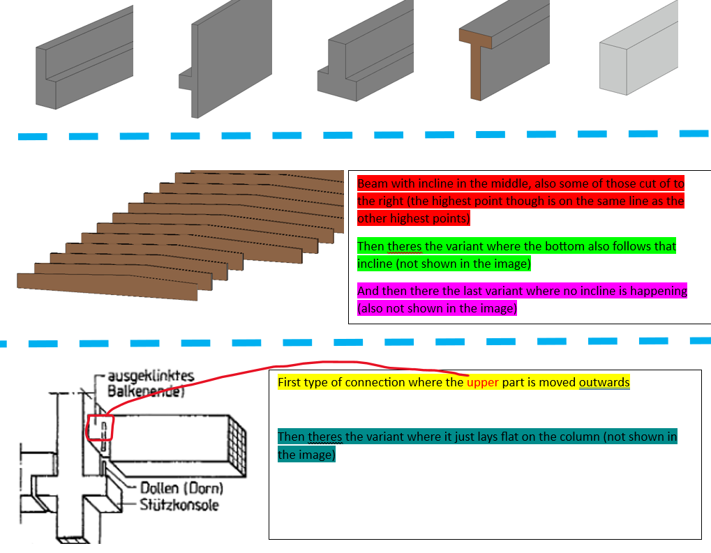
Here´s an example of what I mean by that. I´d like to try to have just one beam family. But that beam can have different shapes, different connections to columns, maybe even an incline, or cutouts in the beam itself. I think this would be pretty hard to achieve with the family editor? Maybe I´m just wrong but I tried another usecase which was far far more simple and I really struggled to get it to work.
Basically there´s this three categories with multiple options inside it. And you can setup any combination of those three categories to design your beam. If anyone knows Archicad Columns, that´s pretty much the same thing I´m trying to achieve.
Not that hard, but you’re making it harder on yourself by doing everything in one family. Even the archi-cad columns (as I understand them) have a few types to pick from, and sizes inside of each - the Revit equivalent of picking a column family for the right profile and then selecting a column type for the size. Your user interface
A simpler option would be to have the designer pick the profile type they want to use, and select the size from there. You build the framework of your family once using the profile of your choosing, and confirm that flexes correctly. Finding the change in depth for the taper is a VERY simple formula (slope parameter * 1/2 of the length). Note that you’ll need instance parameters in the profile to control the parts you want to flex.
The other option would be to use the adaptive components setup, which is more complex and a different UI, but utilizes many of the same concepts. You may have some issues with profile orientation on sloping members, but they’re quite useful overall (doubly so in structure where the repeaters can layout your members on complex forms automatically).
The benefit to what you’re building in the family editor is that the content would be parametric, so if the building gets 6" longer the beam would grow the 6", while the content developed by pushing static geometries into the family would not adjust without starting over, which depending on if you managed your element bindings would mean that all subsequent work on annotations and the like would be lost or have to be manually transferred.