The goal with this is to be able to take groups of cad lines that come in segmented (start/end points) and turn them into a pretty curved line (ideally with a 12’ radius…tbd)
(I’d worked on this a year ago and we’re just now getting around to reviewing it so I don’t have any of the resource links that helped me get this far, sorry)
Part of the issue I’m having I think is from the Group Curves node from Archilab. Sometimes it groups the right lines, sometimes it doesn’t. I’m not sure if that’s error on my part or not.
The export to cad always has “tails” but not just that, sometimes the lines will split at columns or walls.
If it’s 1 single line without any splits or tails, it seems to almost work. (the sorty bit isnt 100% and curves the ends)
I’ve added some description and grouped the nodes. The cad files are inside the revit file. 1 of them has just 1 where 3 lines come together, the other is a typical version of what that plan would look like.
I’m only worried about the “Latitude Tendon” lines.
I can post the cad files if needed as well. Banded Lines Dyn Test - R20.rvt (2.0 MB)
Interesting topic, but as I am not entirely aware of what is meant by ‘latitude tendon’ I am a little bit lost. Structural engineering isn’t my trade, but more my hobby’s hobby if you will…
Instead of latitude tendon just think of it as a random line type for cad/revit, ultimately that’s all it really is for this.
A little more info for reference, we have latitude and longitudinal “tendons” for post tensioned slab design. One goes one way, and one goes the other, and they drape over each other at different calculated heights. Then they’ll pour the concrete, and eventually pull the cables (stressing) and it’ll make the slab flex and allow stability. It’s a pretty neat system.
It’s been a while but I think I was originally looking at that (maybe) but what I’m not sure about is setting a “flowing” radius to the arcs.
Basically as if we were to use a fillet radius in cad of 12 feet.
Honestly though, if it’s close enough that works just as well
This attempts to fillet each polycurve in it’s entirety using the maximum radius (i used 12 for now) and steps down by a given distance until it works or you reach a radius of zero. It then checks if the curves is shorter than Revit’s shortest curve tolerance (3/5 of a grain of sand) and extends the curve by 1/2 of that distance on the start and end if so.
Not sure if it’s what you’re looking for (the branching polycurve you drew above isn’t a thing which can happen, so some sort of rationalization has to occur at some point).
Can you post a snip of the outcome you were getting?
Also I think the test group 1 and 2 can be removed correct? I’ve been checking on this for about 45 minutes and trying the top dwg vs the bottom just to see if there are different results.
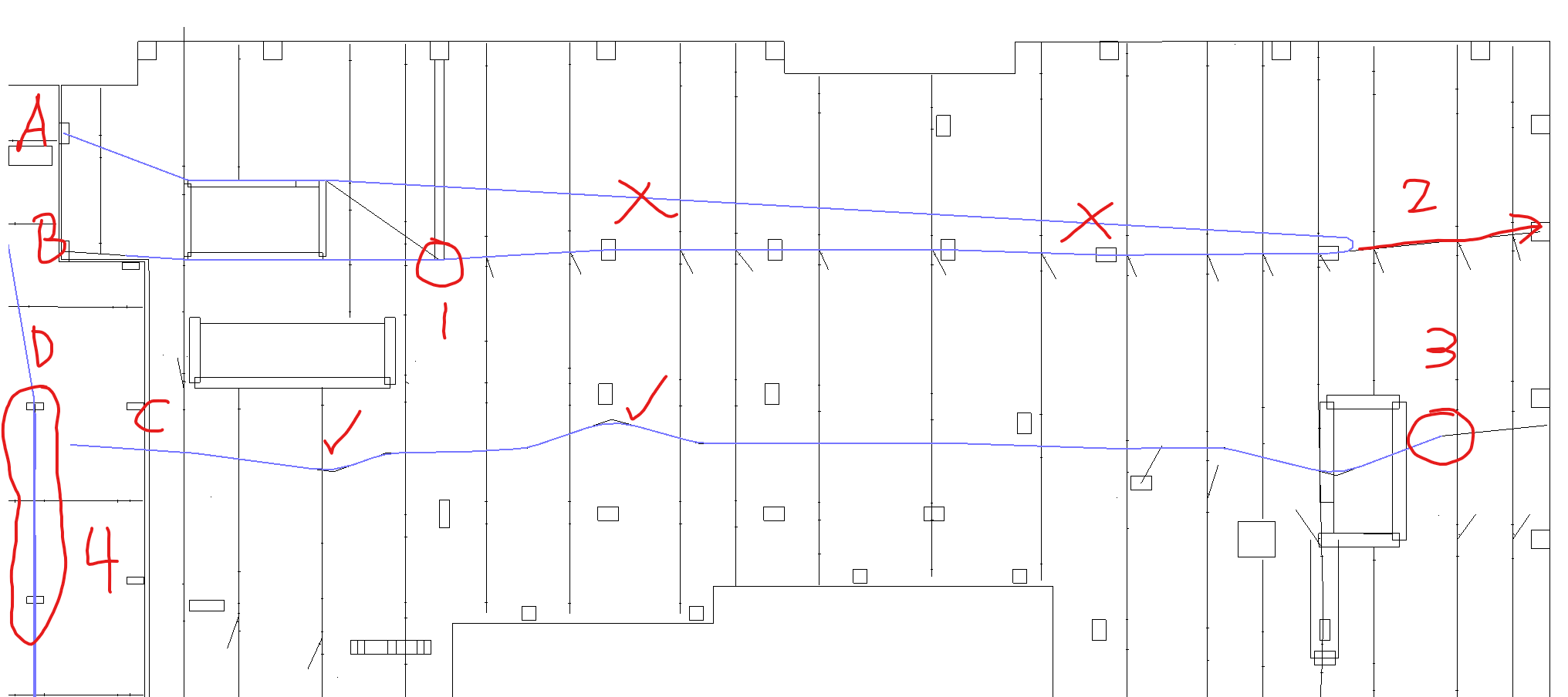
Below is a point list reflected on the plan and the lines I lettered for reference.
Line AB, Is there a way such that if 2 poly curves intersect, to create a “new” radius without changing a previous polycurve radius
I’m not sure why the top line is making a radius with the end of the line, instead of just doing a fillet sim to how line C does below
Why is it not filleting the last line and continuing to the right?
I checked with the cad file and there is only 1 single line on line D but it looks like it tried making multiple fillets to the same line.
Line C at the start is the ideal goal. Dealing with situations like Line A and B are extremely often (where lines intersect)
Not a structural engineer so the logic of this curve with the branches doesn’t make sense to me. Can you outline it with a green highlighter? Or perhaps this is made clear by reviewing the DWG itself?
End of which line? Is 2 supposed to go to the right side of the graphic? Where does it start? Myt guess is that this is a discrepancy in the DWG conversion which is happening in the RVT file, as you are using the unsupported 2020 which I don’t have access to anymore (stripped it for security concerns).
I think this polycurve was filleting correctly for me, but I am not sure where this was taken.
You are importing a DWG into Revit. The data is not a single polyline once you bring it in, as Revit doesn’t have the concept of a polyline and .rvt geometry is different from .dwg geometry (is different from .dyn geometry). Its nearly certain that instead of doing an import you shoudl be querrying the polyline in Dynamo for Civil if you have it, otherwise doing another type of export or dataextraction on each of the polyllines to get the root of the points is advisable. I NEVER recommend working with DWG data in a RVT environment to avoid the same problems you have here.
I’ll look into the original DWG later tonight to see if that makes things clearer.
Something that might help, no fillets should be less than 100 degrees so no u bends
This did get me wondering though, is it possible to have a checklist that looks through the line and if there are 3 points that it creates a fillet for each line as long as the angle is larger than 100 degree’s.
This is the best way I can think to illustrate that.
From the right the 10 and 13 lines fillet into the F=723k b/c the angle is >100 degrees and they don’t fillet toward the 4.
From the left line 4 fillets to the 13 since the angle is >100, nothing happens to the 10 since it’s a straight line, the F=723k gets ignored since the angle is <100.
Your problem is that once you being the files into Revit you have unstructured data which is in effect garbage data, and we all know what they say about garbage in.
Instead of importing the DWG and removing the polyline structure you should be utilizing another means of accessing it. Either out every polyline on it’s own layer, or open the DWG file in Civil 3D and use a ToSolidDef method to pull the polycurves into individuals strings which you can write to files, or pack the polycurves in Dynamo for a civil 3D into a data exchange, data remember node or other interop file type.
When the engineers export their design to cad it’s only as individual lines not a polyline. I’m not sure if that changes the previous message or not.
I was thinking on having the list of curves/points, ensuring both start and end points are grabbed,
then have it do the fillet like we were previously looking at and possibly a while loop(?) such that if there are multiple points (breaks to 2 lines) it will fillet both lines to the previous, then continue down the list of curves/points.
Once it reaches the last or first point depending on the order it breaks and moves to the next line. Essentially just working with the point geometry from the cad file and using Archi-lab.net’s Group Curves,
but one weird thing was Group Curves would usually leave off the start or end point of the curve.
Ok, so when curve A runs into Curve B you want to fillet the two together.
But if curve C also intersects at the same point you want to fillet that to curve A and curve B as well.
And so you have multiple edits to the same curve… it’s a disaster of sorts. Could be doable, but the end result is going to be all over the place.
Print all the curves with a small circle at the start and end point of each. Then with a different color of highlighter for each path trace all the curves - remember the rules of polycurves as you go - no ‘returning’ over a previous curve.
Look at the overlaps and see how things progress - my guess is the drawing will be quite muddy. Remember that one missed line could prove quite problematic.
If this looks crazy when your done, or it’s too hard to keep track of the code, consider asking the engineers to provide the root data. After all they are a member of the project team, and so they should be willing to maintain the structured data when it facilitates project success.