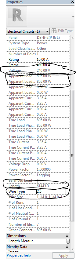
Please help me , i want to add voltage drop parameter to electrical circuits as a result of this formula
voltage drop = PRL/4V^2
and each part of these equation read automatically from properties of electrical circuit where
P= APPEARANT LOAD
L=TOTAL LENGTH
V=VOLTAGE
R= ANOTHER PARAMTER I WANT TO ADD TO ELECTRICAL CIRCUITS and make it read a value i enter.
and fanillay the voltage drop parameter reads all these data and give me a result as aparameter in electrical circuits.
Can anybody tell me how to do this using dynamo.
This sounds as if it would be easiest with a schedule natively in Revit as it would always be up to date. That said, but you could run a script that would calculate the value you are after. Give it a try and we can help you get where you’re looking to go.
i do it already by a schedule and but the equation of voltage drop in the schdule but i want to make advanced thing to make it in circuit to link the result with panel schdule.
So you have the data in a circuit schedule but want to transfer it to a panel schedule?
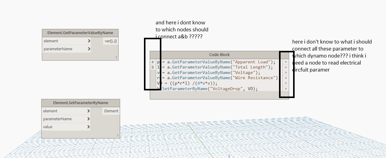
If you really want to do the math in Dynamo try a code block like this:
p = a.GetParameterValueByName("Apparent Load");
l = a.GetParameterValueByName("Total Length");
v = a.GetParameterValueByName("Voltage");
r = a.GetParameterValueByName("ANOTHER PARAMTER I WANT TO ADD TO ELECTRICAL CIRCUITS");
VD = ((p*r*l) /(4*v*v));
b.SetParameterByName("VoltageDrop", VD);
I can’t confirm it works as I’m not in the electrical end of things so no idea if any parameter has an odd unit on it, is read only, or something like that but it’s a place for you to start.
Note that you’ll need to add the other parameter you want to add to electrical circuits prior to getting started.
No I have data in electrical circuits and want to add parameter to electrical circuit to make voltage drop as a result of equation like the photo I upload
I will try this and tell you about the result , thnq 
i try these today but i am very beginners with dynamo so i need your help to which nodes should i connect all these code block input and outputs
You really ought to go through the Dynamo Primer before doing somwthing like this. Do every exercise, cover to cover, and post any questions about that here.
To answer your queation:
First off change the b to another a (I thought you were changing values across categories when I wrote this but you are only dealing with circuits, so the second input isn’t needed).
The input needs to be the elements you want to run this on. So you need to either feed a selected circuit (select model element as one way) or all circuits (all elements of category node would do that), or a filtered list (too in depth to describe quickly - the primer can be your guide there).
I tried my best to make the outputs irrelevant And perform all actions in the single code block - as it is doing the math and setting the values in one go you shouldn’t need to do any more.
Be sure to run this on a test file not your actual job until you know it works. A detached copy of the file should work if you don’t have one already.
Lastly I don’t do this type of work so I have no idea if this will throw an error. Hope it doesn’t but if it does post a screenshot of the warning and your test Revit file so I can try and resolve it.
1 Like
hey King, Voltage drop is already calculated within Revit MEP.
Are you trying to create a user made parameter that calculates voltage drop?
Hi…I think the color for the indicators used to show if the repeat and/or shuffle modes are active should be the same for both of them. I assume you use different colors to highlight that the indicators are for different functions, but both indicators are clearly labeled so there shouldn’t be any confusion as to which is which.