Very distant point coordinates in results from Zero Touch node

Hi,
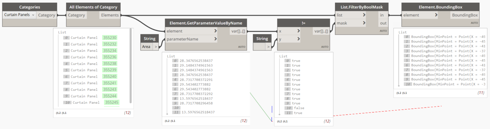
I’m trying to get correct BoundingBox() Min points of a curtain wall’s Panels.
The code is:

GeometryElement panelGeometry = e.get_Geometry(options);
foreach (var item in panelGeometry)
        {
                GeometryInstance geoInst = item as GeometryInstance;
                GeometryElement geoElem = geoInst.GetInstanceGeometry();
                foreach (GeometryObject geoObject in geoElem)
                {
                        Solid solidObject = geoObject as Solid; // Autodesk.Revit.DB here                                                                 
                        XYZ min = solidObject.GetBoundingBox().Min;
                        double x = min.X;
                        double y = min.Y;
                        double z = min.Z;
                        Point p = Point.ByCoordinates(x, y, z);
                        pointTest.Add(p);
                }
        }                           

So I should get 109 points for 109 panels.
The code seems to be working fine, but the wierd issue is:

  1. I have 109 panels, but getting 110 points.

  2. 36 of the points have really “far off” coordinates.
    For example, a “normal” point has the coordinate:
    (-0.762, -0.006, -1.321)

The “abnormal” point coordinates directly from my Zero Touch node are:
(-1000000000000000019884624838656.000000000,
-1000000000000000019884624838656.000000000,
-1000000000000000019884624838656.000000000)
While all the “abnormal” ones have the following coordinates:
(-1000000000000000000000000000000.000,
-1000000000000000000000000000000.000,
-1000000000000000000000000000000.000,)

I guess this is some rounding going on when I Points.DeconstructPoint and rebuild it with Point.ByCoordinates in Dynamo.

Since in the abnormal results all 3 axes are equal, I’m guessing these are somehow Origin points that also get multiplied by an erronous amount.
My first guess is that there are some stranded points somewhere in the 3D geometry, but I couldn’t find them. I tried zooming out a lot, looking at hidden elements, looking at any stray geometry… nothing came up…
Basically before I run the script, the “zoom all” works fine in the file itself and geometry seems normal. Once I run the script, suddenly the file behaves as if it has really far away geometry, so it moves very little with Pan etc.

The second guess would be that somehow a weird coordinate system is set in the code, and is messing up the results because it’s “too big”.

I’m a bit lost as to how to set the coordinate system in my code. I’m sure I can somehow correct these values, but not sure about which methods or classes to use.

Also, I’m really confused as to how a one-point-extraction operation on 109 panels yields 110 results.

Any ideas?
Thanks

What results do you get with the Element.BoundingBox node?

Why are you mixing ProtoGeometry and Revit API methods? Just use the conversion methods and use them right at the start or end of your mainline function. Anyway, thats the first problem as ProtoGeometry units are obtained from your visible units in Revit (I’m guessing mm) whereas Revit’s internal units are always decimal feet.

You might be getting more points than your wall panels as you are iterating the geometry instances of each. Maybe one of you panels has more than one geometry instance and that’s where the discrepancy arises. Instead, just get the bounding box directly from the panel family plus you can cut out the solid extraction which is very expensive and unnecessary.

Change
Point p = Point.ByCoordinates(x, y, z);
pointTest.Add( p ) ;

to
var point = new XYZ(x, y, z);
pointTest.Add(point.ToPoint());

The large numbers look like a rounding issue - basically you have points at file center/0 length vectors probably because the solids are null (so 0 length bounding box) and using as keyword doesn’t throw an exception if the cast fails.

You mean in Dynamo, to use the Element.BoundingBox node on the panels themselves?
I can’t really use that node on the elements I get from my output because I need to convert it to a DesignScript geometry somehow, and ToPrototype() doesn’t work in the code, but also in a Python node ToPrototype() and ToDSType() don’t work…

How can I use that node on Autodesk.Revit.DB geomtery…?

Why are you mixing ProtoGeometry and Revit API methods? Just use the conversion methods and use them right at the start or end of your mainline function

Do you mean the Point.ByCoordinates() method? That’s the only ProtoGeometry one I can see in my code here…

Yep. Don’t mix and match. If you’re in the Revit API context, stay there. Its much faster than ProtoGeometry library anyway, so there’s many reasons why I always recommend this.

1 Like

Thanks.

Actually part of the reason that I went through to the Solid etc., was because the Element, the e as Family Instance, and also the e as Panel all didn’t work.

I’m trying to go directly from them to the bounding box, but I tried the .get_BoundingBox(null) method which they all have as a direct method, and the result is always “Operation Failed”, without a proper message so I’m not sure about the error.

I understand that if I want to get non-view-dependent geometry I need to do it with .get_BoundingBox(null). Am I mistaken…?

FamilyInstance panelFamilyInstance = e as FamilyInstance;
BoundingBoxXYZ bbox = panelFamilyInstance.get_BoundingBox(null);
XYZ min = bbox.Min;
double x = min.X;
double y = min.Y;
double z = min.Z;

var point = new XYZ(x, y, z);
pointTest.Add(point.ToPoint());

Posting this incase it expedites your path to your desired state (deadlines being a thing and all:

There is certainly some value in learning how to do this via Python though, so I recommend turning those leaves over even if this solves your initial issue.

1 Like

Hi Jacob,
Although I appreciate your response, it doesn’t really have to do with the issue. This is because my problem is with geomtery extraction from a Zero Touch node, in C#, and not with default Dynamo nodes.

I could have done what you show here, but I need much more specific selection of panels, according to specific parameters and therefore I chose to use a custom node that I’m writing myself.

I hope someone can enlighten the subject of the post and help me understand why the erronous values appear.

Thanks

@Thomas_Mahon

Technically, the process should be easy if I cast the Element as a Panel, and get the bounding box as shown in the attached image (Revit Lookup screenshot).

I think the “Parameter count mismatch.” is the issue perhaps.

Have you come across this and do you know what the meaning is?

Thanks

No that’s just a setting for modifying the bounding box.

You don’t need to downcast since Panel inherits from Element so you can call get_BoundingBox() thanks to polymorphism. Also inputting null is actually best so long as its a model element and visible in the 3D view.

Just keep it simple; your code looks fine just stop trying to perform unnecessary / incorrect casts. Call the BB method directly on the panel (so get rid of the cast to a Family Instance) and debug your code if its still failing.

Also @jacob.small does make a good point; I typically switch to python for rapid prototyping and use Dynamo + python as a testing ground, especially if the nuances of the Revit API are causing agro (which is almost always as its a total basketcase).

2 Likes

Thanks. Will try to implement what you suggest.

@jacob.small @Thomas_Mahon

It seems Jacob’s approach was a good thing to try after all :slight_smile:
This simple operation yields an error in the file… very strange. Why would it do that?

The curtain panels are of Family: System Panel, Type: Glazed.
It should work fine right? Perhaps there’s another root cause in the file.

How do you think it’s best to test further?

Check that the panels have an area (and therefore a valid geometry) as it’s common to have a curtain panel with no area after merging panels by removing grids. Also confirm that ‘empty’ panels (if you have any) have a bounding box - they may not of they have no geometry.

1 Like

How to check for ‘empty’ panels? :thinking:

Check the area. :wink:

Also the family type.

Hmm… okay, so I found a bunch of panels that have 0 height, 0 area, 0 volume etc…
The literal only difference is that one has indexes 6 and 7 reversed from the other, meaning:

(valid panel)
6-> Design Option: -1
7-> Design Option: Main Model

(empty panel)
6-> Design Option: Main Model
7-> Design Option: -1

Besides that everything is the identical.

But there are a lot of Design Options in the model, with some of them having some panels. Those panels seem to have areas…
I tried deleting all the Design Options completely, purged the file, saved re-opened the cleaned file just to make sure. So now one of the Design Options parameters is gone.
But the situation is the same.

@jacob.small You mentioned that panels are merged and therefore lose their area. Can you expand on that? Is there a way to un-merge them or to see which ones were merged? If I look into the curtain wall editing tools I can’t see anything to indicate that…
Is it something in the Family .rfa file itself?

Thanks

This is a Revit thing not a Dynamo thing, but when you select a curtain wall grid and choose to remove a segment one of the two panels (I believe it’s the later created one in most cases) doesn’t get deleted as the database doesn’t allow a curtain panel to not exist in a given cell. instead the width/length of the panel is reduced to 0 units and as such the area is also 0 units. These panels are automatically filtered out of schedules and such, and without some API wizardry (such as all elements of category), advanced curtain wall techniques (which I’d wager VERY few know exist), or a lucky ‘select by ID’ guess you can’t even tell they are there.

To test this, in a new file draw a simple curtain wall that is say 3 panels high and 4 panels wide. Select all the panels in a row (select one panel, right click, and use the ‘select panels’ drop down to grab the row) and use the ‘IDs of Selection’ command in the manage tab. Copy the ids to the clipboard, and paste them into the a text note or document.

Then select one of the middle curtain wall grid and use the ‘Add/Remove Segments’ command to ‘merge’ the 2nd and 3rd panel into one panel (as if you were putting a transom over two panels). Select the row of panels a second time (using the right click trick) and check the ‘count’ of panels on screen (should be 3) and the number of selected panels (should be 4). Deselect the 3 panels on screen and check the remaining item which is selected - this is your phantom panel. Redo the selection manually and look at the IDs of the 3 panels you can see. Compare those to the prior selection of Element IDs… now try to select (using the select by ID node) the ID which isn’t in the second list. The properties pallet should look familiar.

This GIF illustrates some of that process:

A good solution for this is to filter out panels which have an area that isnt’ greater than 0 (after all, you don’t actually care where something which doesn’t exist is located). One way (a long winded one at that but I’m sticking to basic nodes here) is to use a filter by bool mask thusly:

Note that swapping curtain panels with no area for an ‘empty’ or other basic system panel is a best practice as it can prevent purging what would otherwise be an unused curtain panel. I once inherited a tower model with 100 of such phantom panel types, and used the ‘out’ filter in a graph like this to make them go bye-bye and reduce the file size quite a bit.

2 Likes

@jacob.small

Do you have an idea for another filtering parameter for phantom panels in terms of Parameters, besides the Area = 0 ?
Meaning something like the .Invisible or .IsHidden property, to distinguish them from actual “existing” panels?