Hello
I am extracting some surfaces from Revit elements in order to clean up and freeze the geometry for setout purposes. Since Revit works with solids, when I extract surfaces from walls and roofs (etcetera) there are small slivers at each corner that are left over. I don’t want to have to select all of these surfaces and then have to join the geometry, because that would be a lot of manual work, and I have lots of elements to process.
Here is a sample of what I am trying to do:
I would like to automatically process a list of these surfaces and have dynamo do the following:
- Determine which surface intersects with another surface
- Of the surfaces that do intersect, determine which edges are closest to each other and parallel.
- If the edges are the same leave them alone, if one of them is resting not on the other surface, extend or trim the surface so they meet exactly at the corner.
- The surfaces would also be checked against horizontal surfaces, like the sloped roof in this example, and trimmed accordingly.
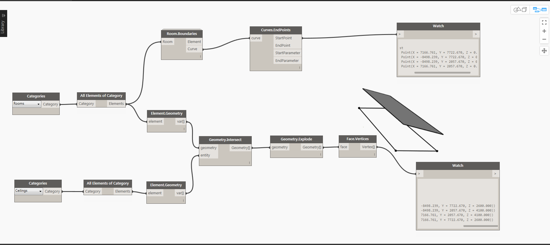
I have been playing around with extracting the surfaces, their planes, finding out what intersects with what, etc. I am stuck trying to figure out how to extend a surface, at a specific edge. I wish there was a trim surface command that worked like the fillet command in AutoCAD with a 0 radius.
I did look into the polysurface fillet command, but that requires a radius and you have to start from a continuous polysurface already, which my disconnected surfaces are not.
Thanks!
David
I guess this was a tough one! Does anyone care to take a stab at this? Thanks.
thinking laterally- you could use room objects
It might be easier rather than trying to reconstruct geometry by intersecting surfaces.
Rooms already have the wall vertices at the base
For ceilings, you could intersect the room with the ceiling
hope this helps
or project the floor points onto the ceiling or roof plane
Andrew
Thanks for looking at this. I really appreciate your time and effort.
Here is why your solution does not work in this case:
I am actually trying to get the exterior surface of these walls, not the interior, which could be described with a room as you suggest. The broader context of this task is that there are multiple of these house like “clusters” inside of a large open warehouse like open office space to the tune of 500,000 sf. So I cant rely on rooms to provide the surfaces I need. Even if I could, the massing on some of these is pretty complex and rooms would not completely describe all vertical and horizontal surfaces.
We use the 3d model as dimensional control, so this is very important because the model will be used in lieu of dimensions on a drawing.
I think the basic limitation is that there are no extend functions for surfaces like there are for curves, which is unfortunate.
See if this helps …
SurfaceEdgeExtend.dyn (14.4 KB)
2 Likes
Vikram
I tried your approach but I get the following result with a little more complicated massing from the project. The other issue is that I need to keep the openings in the surfaces. Please take a look:
Thanks.
David
ok I understand
Although you probably won’t like this approach (since there is extra work) I would keep it simple and place setout markers at appropriate points. Say a face based family.
You could semi-automate the placement with Dynamo
The benefit is that they can be scheduled and readily viewed/checked in the model
Andrew
Andrew
I have looked at this method. There is an Autodesk program called Point Layout which automates this and is pretty slick.
The problem for us is that we need to document the surfaces because we have finishes and other items that need to be tracked. The geometry is just the first part.
By having surface geometry, visual change tracking is also greatly simplified. We can also send this geometry to contractors so they can create their construction models from the surfaces. We want to dumb the geometry down because it allows us to overcome some of the downsides of Revit’s automatic cleanups, which often create dirty geometry. The surfaces are a “cleaned up” version of the geometry that is frozen at a certain point in time and issued for construction.
Maybe a bit off-topic, but yes, Autodesk Point Layout and the Trimble equivalent are not bad.
However, I’ve never been able to convince people that it is worth $1000 per 3 months (APL) on top of the Revit/Navisworks licence, despite obvious issues of saving time/reducing errors.
Hi David,
You’re asking for a solution to a very specific corner case. You’ll get an answer much faster if you provide as much information as possible head on. Right now you’re wasting everybody’s time by forcing them to recreate your work from scratch.
Consider sharing a simplified Revit file that showcases your starting conditions and a simple Dynamo graph with your current progress.
Dimitar
My apologies for “wasting your time.” I was giving a simplified version of the problem to keep the discussion focused. I have attached the iterations I have tried so far, the test Revit file (Revit 2016 format) and a screen grab of the scope of the project. What you see in the screen grab is only the interior portion of the exercise. There is an equivalent portion of this task for the enclosure of the building, which has sloping surfaces and complex geometry.
I actually don’t think this is a corner case at all. Extending and trimming geometry should be a pretty basic feature of any modeling software.
Regards,
David.
Dimensional Control Surface Extract - Native Solids.dyn (15.9 KB)
Dimensional Control Surface Extract - Native Surfaces.dyn (55.3 KB)
Dimensional Control Surface Extract.dyn (37.3 KB)
Dimensional Control Surface Build v1.dyn (9.6 KB)
Extend or Trim Surface Edges v1.dyn (16.2 KB)
Extend or Trim Surface Edges v4.dyn (10.6 KB)
Extend or Trim Surface Edges v2.dyn (21.4 KB)
Extend or Trim Surface Edges v3.dyn (14.5 KB)
Merge Coplanar Surfaces.dyn (21.0 KB)
Geometry Extraction v1.rvt (1.4 MB)
Geometry Extraction v2.rvt (1.5 MB)
1 Like
@David_Pointer
Everybody’s got their own point of view. I’d personally prefer to stick with “key” points when coordinating models and avoid the more complex surface geometries. Now that you’ve shared your files with me, your intent is much clearer to me. I definitely agree that it would be nice if we could trim and extend surfaces but I can’t quite imagine how that would work from a visual programming aspect. Trimming, extending and aligning are manually intensive tasks that require multiple user inputs for each individual action.
Here’s one possible solution that uses what’s already available on the package manager. All custom nodes are from the spring nodes package. It will work for the specific model that you shared but will probably need some tweaking before it could work on a project-wide scale:
Hopefully now that you’ve shared your sample files, somebody will come up with a better approach than the one above.
3 Likes
If you are just interested in exterior surfaces, then you might want to try topology traversal. Face.AdjacentEdges() & Edge.AdjacentFaces(), and then use filter to filter out the bottom face based on it’s z value.
Dimitar
This is a pretty ingenious way of solving this problem, and it works pretty well with the test geometry. However I tested it with a sloping roof shape and the tower walls failed to patch as surfaces, but this gets me started. The sloping geometry will be on the exterior not the interior, so I can make do with this and figure out the rest later.
By the way we use CATIA in the office and another group has a script that does this very same exercise. Each surface is its own part and the script iterates on each edge, figures out which ones are close to each other and parallel, and then extends or trims the surfaces as required.
I am trying to do this all within Revit so that we can save the time and effort it takes to export to CATIA in order to deliver the 3d model to the contractor.
Thanks
David.
Sharad
I will give your suggestion a look. Thanks.
Here is my attempt. In it’s present state works only with simple blocks.
SurfaceEdgeExtend-20160610.dyn (6.7 KB)
Thanks Vikram, I will take a look at this method as well. This will help me learn designscript.
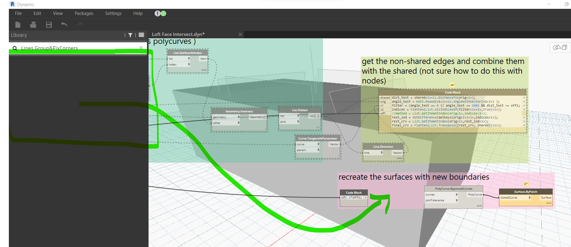
I came up with the following script, after looking at some actual cases in my model, and the reality that the geometry may get more complicated as the project develops.
I can summarize it as follows:
- Get the faces that you would like to use for setout documentation.
- Get the Revit elements corresponding to those surfaces.
- Get the solid geometry of those elements and union all of them to each other. Since Revit has already cleaned up the corners this gives us the clean geometry I was going for.
- Explode the joined solids, and find the surfaces that correspond to the select faces on step 1.
- Get the type and family names of the original Revit elements.
- Use this information to name and create mass families with family names that correspond to the category, type mark, elementId, and a time stamp for revision tracking.
The workflow above can handle almost anything we can model in Revit. The only downside is sometimes we get extra surfaces that align with the initial picked surfaces. At that point its just a matter of deleting those after running the script. Here is a screenshot of the result where I run the script to create an exterior and interior dimensional control surface, as well as the definition itself.
Thanks,
David.
Extend or Trim Surface Edges v6.dyn (50.0 KB)
Geometry Extraction v1.rvt https://db.tt/6pPFfSbM
Geometry Extraction v2.rvt https://db.tt/wmQygYsZ
4 Likes
Hi @Vikram_Subbaiah
I am using revit 2020 and the built in version of dynamo that ships with 2020 revit.
I have been trying to adapt your scripts in a effort to create a closed solid with volume which represents the intersection of faces that a user selects directly from isolated geometry in the 3D view.
In the end I would like to calculate the volume depending on a series of faces that the user of the script selects.
I was wondering if these scripts which you have written could assist me here or if you have any ideas. You will notice some of the faces of the geometry is sloping - which I am aware is tricky to build from.
Thanks!