I’m working on a new challenge and could use some help. I need to create a routine where the user enters the width and height of a rectangle, and then selects a 3D Polyline.
Based on this input, I need to create a sweep, applying the rectangular section along the selected 3D Polyline. However, there’s a key issue: the Sweep command always uses the center of the profile to generate the solid, but I need it to use the top-left vertex of the rectangle instead.
This is important because the 3D Polylines I’m using do not represent the central axis of the objects I’m modeling — they actually represent one of the edges.
Any suggestions on how to achieve this or workarounds would be greatly appreciated!
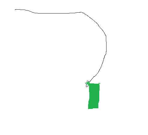
Sorry for the sketch, but the idea is to take a topographic survey, use the 3D polylines that represent the curb, and create the extrusion according to the drawing.
Hi Jalo, I’m not sure if I understood correctly, but in this case is it possible for me to choose the vertex along which the profile will follow? Or are you suggesting that I move the 3D polylines so that when I use the sweep, it comes out as desired?
Yes you can pick a vertex, but your selection criteria has to be strong enough to take the right point.
Now that we know that you want to extrude a curb from a 3Dpoly you get from topo. You could take the Back/Face of Curb line (which you are pointing) and use it as path. If, by any chance you don’t have that line, filter the points that belong to that spot (maybe the topo identifies as “FC”,“BC”), create the poly and then extrude
Sorry, but I still don’t understand. Could you send an example of the code you showed in the image? The surveyor has already sent the 3dpolys that represent the upper left top, now I would need to create a code where I can input the rectangle dimensions and specify which vertex the sweep will follow.
They key nodes are already shown in the picture, the only thing missing is the path , which is your polyline. I think it is now on your side to work a little with Dynamo nodes.
Looks like the object selected is right in the center of your profile.
You can either transform your path by moving the path to the desired point (may get some inaccurate points when curve applies due to offset) or generate a line in your cad file that correspond to your desired path and select that poly.