Hello,
I have a solid from a dxf-import that looks like this
i need to split the geometry to individual buildings
below i explode the geometry, get the top faces and the bottom faces to make new individual solids or forms. FormByGeometry or Solid by loft (cross sections)

problem is that my lists are unequal (why?)
I played with the geometry settings large and extra large, doesn’t work.
Any suggestions on better ways to do this?
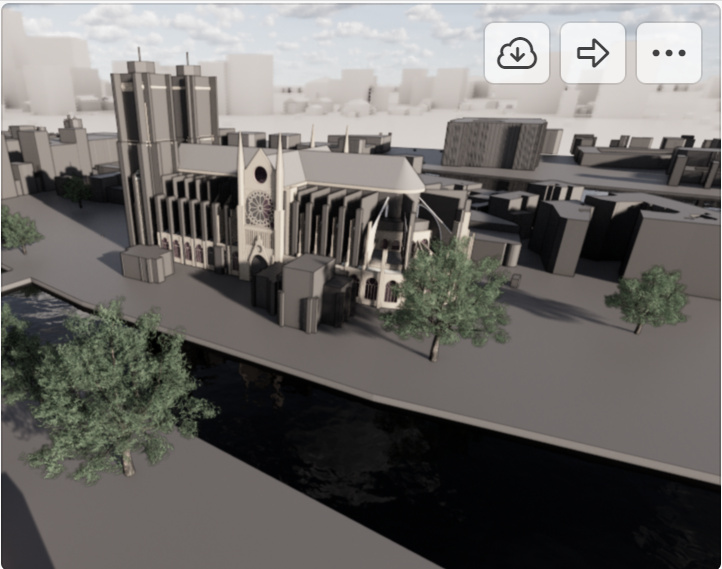
it looks like every building has a groundsurface, but the church has more than 1 upper surface
Edit:
My first idea:
- get all ground surfaces
- loft ground surfaces to 100m
- intersect these solids with every upper surface
- group the intersecting surfaces and make a polysurface
- loft between ground surface and polysurface
1 Like
Reading the blocks/solids directly with the LinkDWG package might be more efficient. If you post a small sample dwg (not that full neighborhood but maybe just the block around the church?) I can have a look at the how later today. 
1 Like
here is a sample
3DView-{3D}.dwg (371.5 KB)
1 Like
Hey Marcel,
Just my few thoughts…
Perhaps the surface normals aren’t == Z but only quite close? Could you do nearly == ?
I might get the bottom surface outline and extrude as solid by the height of a vertical… at least you could easily see the ones which work and visually check discrepancies?
You could also use Dynamaps to pull a topo and (even more) building outlines with no effort…
Hope that’s of interest 
Good luck,
Mark
1 Like
show me, when you have the time.
i’m interested
the nearly idea is ok, but that would give me more mismatches?
I’m out of the office now… but will see what I can squeeze in tomorrow…
It looks promising for extracting height data with open street map, along with the buildings, trees, roads etc. as clean geometry…
Dynamap & Elk should work well…
1 Like
Question: can I leverage Civil 3D 2020 and Refinery (just for the Remember node) here? If so I appear to have a working solution. Sadly LinkDWG fails to read the solids correctly in Dynamo.
Soooooo…
This is a concept I’ve been toying with for awhile. I’m a HUGE fan of the remember node in Refinery, and this workflow is a prime example of the potential. I say workflow because it’s actually a single graph but needs to be run in two environments - first in Dynamo for Civil 3D, then in Dynamo for Revit. Crazy I know, but hear me out as this is a bit crazy.
-
First I opened the file in Civil 3D 2020 as AutoCAD. I had to clean up the CAD file to merge the surfaces to solids - doable with Dynamo but time to put into this effort was at a premium today. Deleted the bounding box, editing the block, selecting the street lines and deleting them (you only asked for the buildings - again time), then selected all of the polyface meshes which make up the building faces and used a convtosurf command, and then selected connected sets of buildings and used the surfsculpt command to create a watertight solid from the selection. Finally I selected all of the remaining surfaces and deleted them. Finally I exploded the block - giving me individual solids for each building / city block in model space. Took about 5 minutes total including the time to repair a bad mesh or two. It’s shocking how handy some of the AutoCAD tools are for data parsing. It might have been faster to use a ‘group surfaces’ technique in Dynamo similar to the classic group curves which @Vikram_Subbaiah illustrates here, but again, time.
-
I then launched Dynamo in AutoCAD using the AECCLAUNCHDYNAMO command (since I’m in Civil 3D as AutoCAD I don’t get the ribbon button), and placed the following nodes:
This gets all solids in the model space of the current AutoCAD document, and returns their geometry as Dynamo data, before passing it onto the Remember node. Data is then saved into the dyn when I save the graph (gotta love those element bindings eh?). I think close out Dynamo and Civil 3D and move back to familiar territory, launching Revit and creating a new project (glad I checked the units while I was in AutoCAD - needed to be in Metric).
-
In Revit, I launched Dynamo for Revit and opened the graph I created in Dynamo for Civil 3D. Looks like this, which usually would be scary, but it was by design in this case.
All those unresolved nodes are part of Dynamo for Civil 3D, which have no business interacting with a Revit model anyway. The important part is that the Remember node remembers the geometry from the dwg. Add a few of the more standard Revit nodes…
Data passed from Civil 3D to Revit cleanly and quickly.
Total time to clean the dwg files, build the graphs and create the Revit elements was less than 30 minutes (sorry for not turning off the Dynamo preview geometry.
13 Likes
first result of another workflow
Thanks to all

4 Likes
Great work Marcel & Jacob
Apologies for the slow response,
Just for completeness, here’s my go at the DynaMaps / Elk version… Not polished at all, just of a small area, but if you wanted a bulk backdrop of a city, it gives a flavour… it’s automatic, accurate & free… The interface is quick, but my PC is slow!
Obvs Topo is a funny thing… it’s not going to work with a River that has a vertical edge, but often it’s quite useful.
I threw in a few passthrough nodes that might not be needed.
Hope that’s of interest,
Mark
DynaMaps for Marcel.dyn (192.5 KB)
6 Likes
Really good stuff in this thread. I have a few thoughts on the work you presented @Mark.Ackerley :
- Moving this geometry into FormIt instead of Revit would allow for fast clean up and detailing. You could then bring the FormIt content into Revit as families quite easily. Quite nice for when you don’t yet have the detailed model such as the one @Marcel_Rijsmus posted.
- Dynamo allows for processing data from multiple sources before recording the result. so in theory you could get topo from source 1, and building outlines/heights from source 2, modify buildings so they sit on the topo, and write one set of data into your context modeling software.
1 Like
Hi Jacob,
Everything you say is true
-
I would love to give formit another go, I’d be keen for Autodesk to come give a hard sell to my firm, I couldn’t get it moving last time, but that was before it became integrated into the design collection (or whatever it’s called).
-
My previous workflows for these kinds of tasks were dislocated and not so easy for a casual user to navigate.
The cute thing about DynaMaps is it’s giving you a single, really great interface to bring in high quality opensource data from a couple of sources …
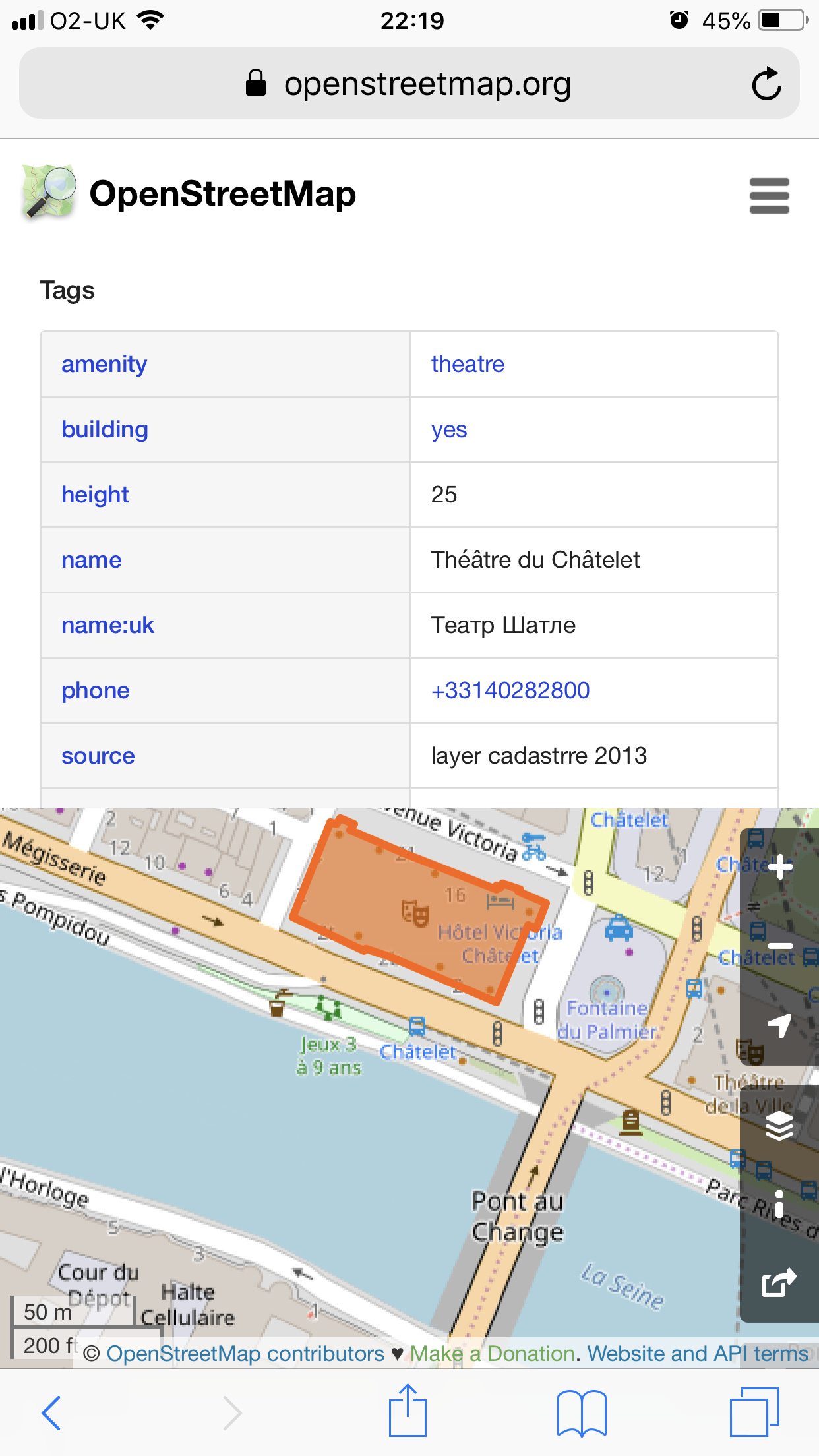
Openstreetmap has vector information for buildings, streets, etc. as well as embedded information about heights etc.
The topo is bring brought from SRTM from NASA…
Right now, I’m using Elk to make more use of that info, but I believe that the next version of DynaView will bring a lot of enhancements to reduce that dependancy. But yu could absolutely bring in other info as well.
My attempts at making the lines and buildings sit on the topo were not great… Grabbing a polysurface and intersecting 1000’s of lines is slow, and the results were not very robust for making closed polycurves for extruding. So I intersected points and made lines from those, faster but not as accurate. The buildings I moved up, rather than properly intersecting, so again not perfect.
As I say, the overall effect is rough, but probably good enough for a background view, to work with the detailed foreground stuff… I’m imagining that the shear scale of bringing in a square mile of city for example would create enough impact…
Hope that’s of interest,
Mark
3 Likes