I know we’ve been talking about this before, and I know that there are ways around it like exporting to cad and importing back again, but I’m not a fan of that.
I have this section view, that I need to convert it into a drafting view. I worked on something but there is an issue at the end, you can see attached. If someone can please take a look and let me know what they think. Thanks!
I am curious as to why you need to do this - what is the larger project workflow?
Asking as every solution I have seen in this space results in issues but when the larger workflow has been examined a scalable and consistent path was able to be found.
Hello Jacob, the larger workflow is, when we have a detail section, which we put some annotation on the model, we’d like to save it as a drafting view and make it a typical detail, for future use. we can only copy the annotation part into a drafting view, but we need the assemblies and opening to be copied as well since they are the main elements. what do you think is best? just as a reminder, im against exporting to cad and importing again.
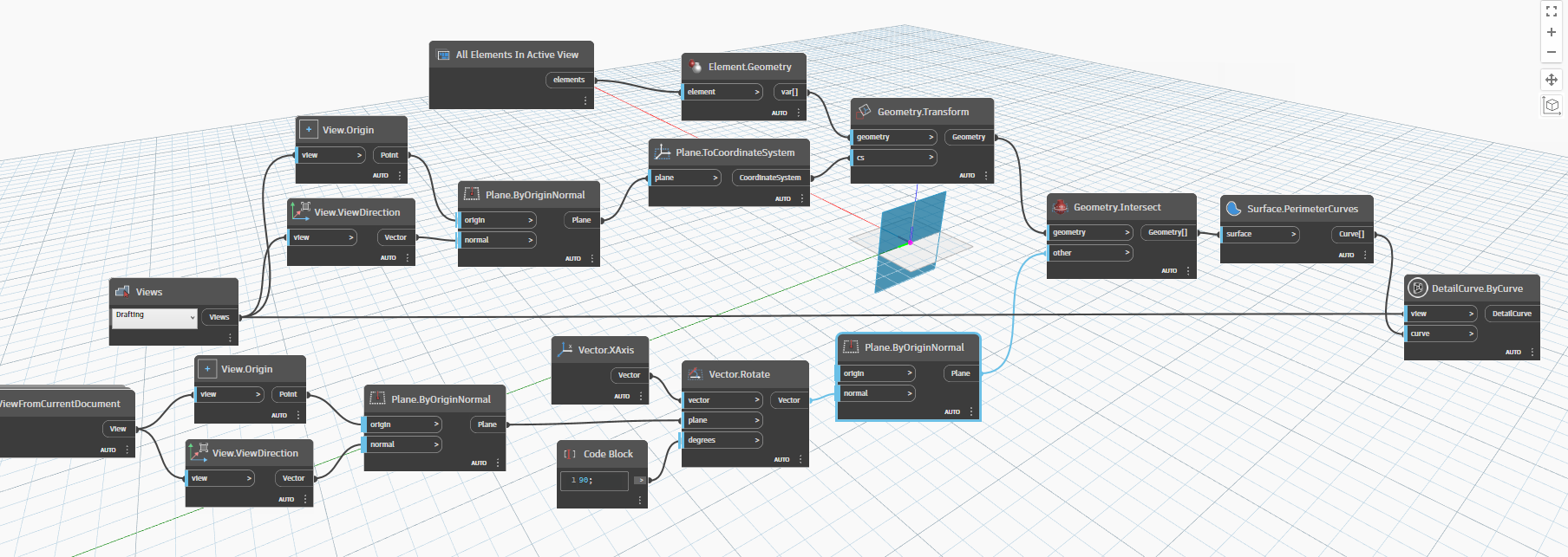
Ok I LOVE this as a concept to kudos for the insight. I don’t have my CPU with me at the moment so I can’t see your graph (if you export your workspace as an image it would help)
Since lines are being created anyway you are going to have to do some line creation to start with and you want them in your firm’s standards. This is likely easiest in the Revit UI but you can use the API to extract the linework just as well but the UI is far easier.
UI steps:
Set the model to half tone or another easily identifiable method.
Insert a pair of reference lines which will become your origin.
Trace the model components using the line styles you want.
Group all the linework and annotations - make sure there aren’t any tags on model elements.
Set the group’s origin to the reference line intersection.
Place the group into a new typical detail.
Bonus points I believe there is a way to move the group to a family (don’t recall how offhand but it is doable) for reuse in other models and in larger scale section views.
In an automation the process would be similar, but extracting the linework is the hard part. I don’t know of any nodes for this, but ideally you would retrieve the geometry from the element in the context of the view, but you could also use the newer Dynamo for Revit releases to pull the geometry at the detail level of the view. This won’t extract layers of the walls and such, but you can generate parts and use the geometry from those if needed. Ideally I would want to replace that content with detail components though.
Once you have the geometry, discard anything except solids, and then you can intersect it with the view plane and extract the perimeter curves thereof. If you maintained your list structure you can then assign a line style accordingly.
Lines in the distance can be extracted as well, but I would focus on nailing down this work first.
From the geometry node (not sure what package that is from but nice find) filter out the non-solids with a List.RemoveIfNot node.
Take the resulting solids and intersect them with the plane you constructed from the view.
From there you will have a list of surfaces - extract the perimeter curves.
Each of those curves needs to be converted to a ‘cut’ line in your detail view - I think there is a constructor for detail curves in clockwork named something like DetailCurve.ByGeometry Which can do this. Note you may want to trim them to the view’s extent, but get that linework created first.
Missing the transform to the XY plane by the looks of it. I think there might be better a better node for drawing the detail curves too - which package is that from?
it works, thank you brother! you are a genius! i truley appreciate your help and guidance.
a few issues tho,
1- depending on the section orientation, i have to rotate the vector so it follows the drafting view.
2- it doesnt follow the crop region of the section and draws the entire model which is not ideal.
3- it doesnt recognize the openings like doors, windows and wall openings.
4- it doesnt draw the common edges of the assemblies and draws only the perimeters.
5- it only draws the cut lines and not projections lines within the far clip offset of the section
are there any solutions for any of them? please let me know what you think, thank you again!
Transform the result of the intersection node instead of the initial geometry. This should be the transform node which takes two coordinate systems - the first (base coordinate system) should be derived from the core plans and the second should be the identity coordinate system.
Get the crop region, patch it to a surface, transform it to the view (if needed) and intersect that instead of the view’s plane.
Openings should intersect if they are crossed by the section as the wall geometry (and window/door geometry for that matter) will be cut.
The line work which makes up detailed views of system families don’t actually exist but are drawn as an overlay by Revit (things would be exceedingly slow otherwise). Make parts before you generate the view (or do so in the graph) live without them, or proceed to item 5.
This method is a start, and doesn’t take into account everything needed to get started. I get the desire for what you are after, but since you are already annotating the view you will likely need to annotate the stuff in the back as well as there is not an easy way to get that out of a view. That said every ‘Typical Detail’ I have seen that benefits from being a drafting view doesn’t need the stuff in the back of the view - only the section, as what you see in the background won’t likely project consistently in other section views and ‘typical elevations’ for windows and such are best built as live model view of the window in question (one per window type / window treatment). Good families can also expedite the ‘in the distance’ efforts, and good detail components can make sort work of the wall graphics (again your workflow above indicates you were doing that type of work - use a detail component and create an instance of the group in the new view). To catch everything you have listed here would not only take ages to build, it would also be far slower than the DWG export and import AND require about 2 months of code maintenance for the multitude of edge cases which will have to be dealt with and updated annually (and consistently growing as each release will add more) - visibility upkeep is a very big part of what Revit does.
1- no matter what, i feel like i have to do it manually every time, since the section is flipping and also the degree input is a manual input.
2-i tried to get the crop region but but neither the size matches, nor the location when it’s drawn in the darfting view.