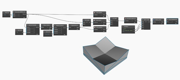
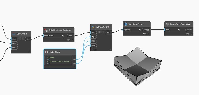
Hi, I’m trying to follow along with the Primer 2 - Coding in Dynamo - Python - Python Nodes - Exercise: Custom Node with Python Script for Creating Patterns from Solid Module.
When I followed along with the example I got error messages until I changed the value on line 43 from a 0 to a 1. That got me to the attached screen shot. However, it still doesn’t look like the image in the Primer example. I tried changing the values on line 42, but that wasn’t good.
Any help would be appreciated, Thanks.
@jeremy.johnsonA52G9
so check the lacing of your nodes too set it to longest ||\ i see also check if you have to hide some nodes ( not showing geometry).
Which version of Dynamo are you in? Can you provide your current code formatted for reuse here (use the </> preformatted text option in the gear menu) so that we can review? Lot of work retyping from an image otherwise. 
# Load the Python Standard and DesignScript Libraries
import sys
import clr
clr.AddReference('ProtoGeometry')
from Autodesk.DesignScript.Geometry import *

# The inputs to this node will be stored as a list in the IN variables.
#The solid module to be arrayed
solid = IN[0]

#A Number that determines which rotation pattern to use
seed = IN[1]

#The number of solids to array in the X and Y axes
xCount = IN[2]
yCount = IN[3]

#Create an empty list for the arrayed solids
solids = []
#Create an empty list for the edge curves
crvs = []

# Place your code below this line
#Loop through edges an append corresponding curve geometry to the list
for edge in solid.Edges:
    crvs.append(edge.CurveGeometry)

#Get the bounding box of the curves
bbox = BoundingBox.ByGeometry(crvs)

#Get the x and y translation distance based on the bounding box
yDist = bbox.MaxPoint.Y-bbox.MinPoint.Y
xDist = bbox.MaxPoint.X-bbox.MinPoint.X

#Get the source coordinate system
fromCoord = solid.ContextCoordinateSystem

#Loop through x and y
for i in range(xCount):
    for j in range(yCount):
        #Rotate and translate the coordinate system
        toCoord = fromCoord.Rotate(solid.ContextCoordinateSystem.Origin, Vector.ByCoordinates(0,0,1), (90*(i+j%seed)))
        vec = Vector.ByCoordinates((xDist*i),(yDist*j),0)
        toCoord = toCoord.Translate(vec)
        #Transform the solid from the source coord syste, to the target coord system and append to the list
        solids.append(solid.Transform(fromCoord,toCoord))

# Assign your output to the OUT variable.
OUT = solids
I don’t know what the gear menu is, so I just copied and pasted the text onto the reply above. I’m still very new to this. Also I attached the image of the graph in case that helps.
The Dynamo version is v.2.19.3
1 Like
The code you provided above (with a 0 in line 42) is working fine for me in Dynamo 2.11, 2.19, and 3.4:
Can you show the error you’re getting? Have you retyped the Python from scratch instead of copy/pasting it and therefore I’m missing something?
1 Like
I noticed on your graph the list create only has two wires. On the one in the primer it has three. I tried to duplicate the way you have it but wasn’t able to reach the same result.
I like to reduce the number of nodes anywhere I can, as it makes things execute faster and uses less RAM. In the case of the primer the exercise takes two polycurves, builds a patch of the first, builds a patch of the last, and builds a loft between each. These are done as individual actions and then joined into one list of surfaces and the solid created.
In my graph I build the list of the two polygons- one for the base and one for the top. I patch them to get two surfaces, and loft between them to get the edges. One list doing both actions. The two are then combined into one list using a List.Join node (not a List.Create). This might not be much if even any of a performance improvement in this simple case, but it’s how I prefer to work.
In any case, the result at Solid.ByJoinedSurfaces it will be the same between the two strings of nodes. Disable the preview on the Python node and expand the data in the Solid.ByJoinedSurfaces node to make sure you see just one wedge shape, and then we can narrow it down to your python code.
1 Like
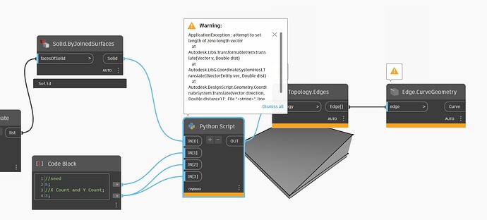
It looks like there is only one solid showing up in the Solid.ByJoinedSurfaces node. Also, I attached the first part of the warning in the Python Script node.
Can you post your .dyn file?
Primer2_9.10.1.dyn (34.2 KB)
Here you go.
Hello, there!
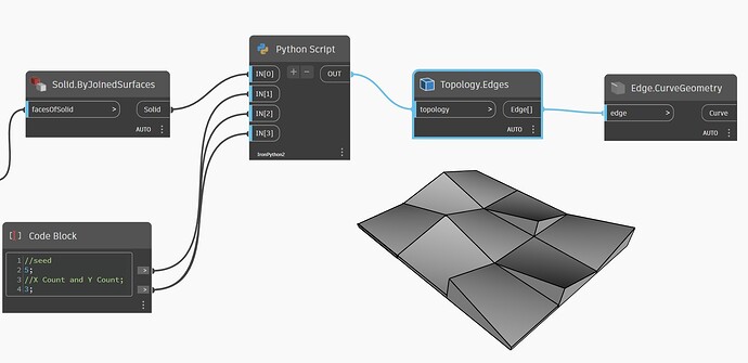
I gave it a try using the primer tutorial, and noticed a difference. The Python node uses IronPython2, while your graph uses CPython3.
I tested it, and while CPython 3 also resulted in an error, changing the engine gave the correct results.
Cheers!
Edit: I don’t know the difference between engines and how they affect the code or why it works in one of them, but not the other. I guess @jacob.small could help with that.
Yes, that was the problem.
Thanks so much!
1 Like
I just took another look at the Primer 2 graph. All of the images show it as being CPython3, but it only works for me if it is IronPython2. I guess I’m still wondering where I went wrong and how I can follow along with the Primer.
2 Likes
Checking is still on my todo list. Traveling this week to Oslo so I am a bit delayed. My guess is the issue is with the imports not the main portion of the code, but I may be off. I did the exercise with CPython though.
The Primer with coded copied verbatim also works with CPython in my test 
1 Like


