Hi to all,
I’m trying to make a dynamo node script to create a multiple rows polar array.
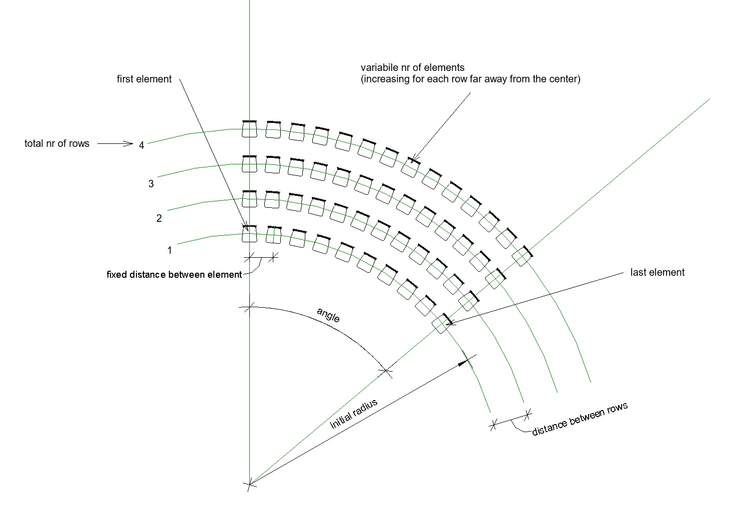
I know there are several ways to create the first row, the problem is creating the other rows and set distance between rows and increasing elements for each row far away from the center.
Attached a manually created example.
Many thanks for any idea or solution.
2 Likes
1 Like
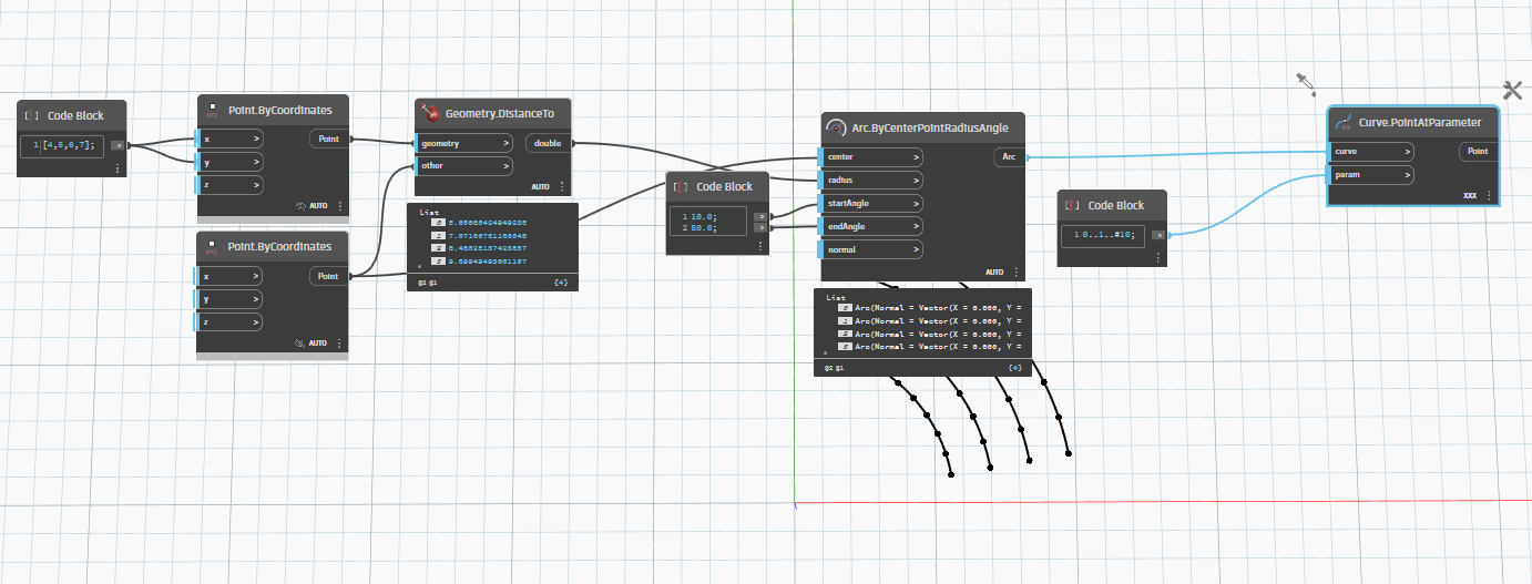
Here’s two solutions, one using a designs script definition and one using nodes. Both allow the spacing between seats to flex so that you always have a seat at the middle of the curve and both ends. If you want Revit families at these locations look into your options for creating a family instance at each coordinate system.

2 Likes

I’ll try as soon as possible… I’ll let you know.
Many thanks.
how to deal with your code?

def polarArray(
				origin: Point,
				insideRadius: double,
				rowCount: int,
				rowSpacing: double,
				startAngle: double,
				endAngle: double,
				normal: Vector,
				seatSpacing: double
			)
{
	radii = insideRadius..#rowCount..rowSpacing;
	arcs =
		Arc.ByCenterPointRadiusAngle(
			origin,
			radii,
			startAngle,
			endAngle,
			normal
		);
	len = arcs.Length;
	firstHalf = 0..len/2..~seatSpacing;
	secondHalf = len/2..len..~seatSpacing;
		lengths =
			List.UniqueItems(
				List.Flatten(
					List.Transpose(
						[
							firstHalf,
							secondHalf
						]
					)@L3<1>,
					-1
				)@L2<1>
			);
		seatCoordinates =
			Curve.CoordinateSystemAtSegmentLength(
				arcs,
				lengths
			);
		return seatCoordinates;
};
there is still an error
KR
Andreas


1 Like

This isn’t required by core, but can be introduced by integrations (ie: Dynamo for Civil 3D, Dynamo for Revit) or by packages (ie: Orchid).
Not that I know of. I just utilize the forum for the stuff I post as this is already a full time hobby. ![]()
Anything which utilizes at parameter will fail to insert the extra seats in the subsequent rows. Everyone will look at the back of someone’s head if looking center stage, except for the first row.
1 Like
hehe you are right…i need to go more out specially to stadiums ![]()
3 Likes
anyway when there is a goal everyone gets up and we can’t see anything and the glass of beer flies too
cordially
christian.stan
3 Likes
Hi Christian,
this works, but each element has original coordinate system.
I’ve tryed to use the node Curve.CoordinateSystemAtSegmentLength but it doesn’t work.
Any ideas?

1 Like
Sorry @Draxl_Andreas but unfortunately my dynamo knowledges are limitated. I’m new in coding with dynamo.
I’ve worked on @christian.stan example and found a way to add some nodes to simplify input data process and everything works fine, but for me this step is complicated to solve.
1 Like
hello, here is a post drill as an example

don’t forget to switch to manual for setrotation
following information from Mr. Andreas

Cordially
christian.stan
1 Like
Instead of using family instance by point and then editing the rotation, utilize the FamilyInstance.ByCoordinateSystem, which will set the rotation as you go.
Looks like this:

Note I haven’t implemented the FamilyInstance.ByCoordinateSystem node or rotation of the coordinate systems to suit the family I used on the Design Script version.
DYN for testing: Seat Array.dyn (1.1 MB)
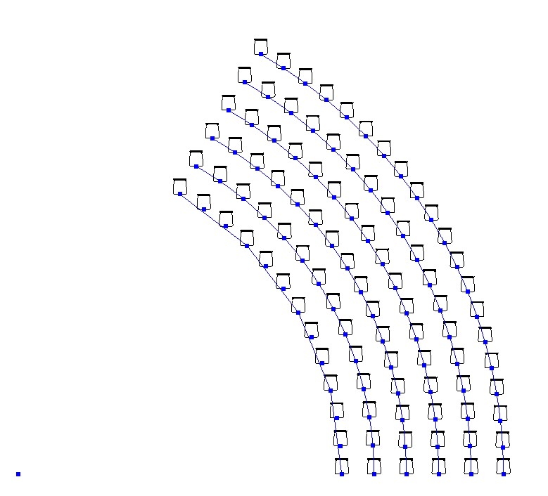
Edit: Forgot to post the results:

3 Likes

Weird, I don’t have your inconvenience

Go rather on the script of Mr. Jacob it is better thought out and built
Cordially
christian.stan
All of the scripts will need to be tailored to your chair family. In my example the chair is aligned to the origin. Your family appears to have the origin point in front or behind the chair by some distance. The graph will need to take this into account.
1 Like