I have a dyn file that allow me to place several families in a revit file by coordinates and by controlling the space between each element.
I would like to place them on a grid of point instead of a looooong line by setting how many columns there is f.ex. Dynamo would place 4 and then go “to a new line under” and place 4 others etc.
I manage to do a grid but it duplicates the objects… so if you could just put me on the way, give me a hint…
Here is the thing. Don’t know if it’s really good but it works great for now, I just would like to place the families in a grid-like way instead of all in a big long line. Something to do with the coordinates I guess but I can’t think of a solution, I am new at this…
Don’t do the job for me, just put me on the way if you’ve heard about it! (I can post the python if needed buut I doubt it has something to do with the placement…?)
It seems you are creating a diagonal series of points, not a grid. Why don’t you try to feed your List.Combine with a grid of points? Does it works if you change the lacing of Point.ByCoordinates to a CrossProduct?
I would like to have one family instance by point instead of duplicating them. The must would be to control the width of the grid, say input 5 as the number of columns and the grid creates itself according to how many elements has to be placed.
I understood what you’re trying to do, and you just confirmed that the lacing is something unclear. You used a crossproduct in you PointByCoordinates node. In the X input you put a sequence of 12 elements coming from your python node. In the Y input you wrote “0…10000…1000”, which means 11 elements. With the cross product you create a 12x11 grid. The distance between each element depends on the “step”, so in your case is “2000 units” for the X direction and “1000 units” for the Y direction.
So, if you want a 5x5 grid you need to use a “step” that divides your range by 5, or simply use another sintax: “0…whateverYouLike…#5” In that case your grid will have 5 elements in the desired direction.
Is that clear? Try some exercises with points only, control your grid, or your generic distribution of points (on a curve maybe) and then placing families would be very easy.
I played a bit with the points and I think I get how it works. I didn’t even need to connect the python/sequence to the X input of PointByCoordinates. I can create a grid with two code blocs "0…WhateverILike…#5” and the FamilyInstanceByPoint place the objects.
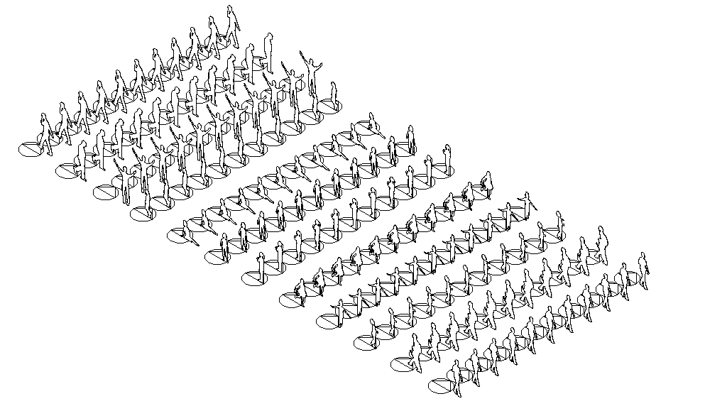
BUT I still have a little issue: whatever grid I try, I get several lines of objects that are the same family (6 lines of 6 times “nameofthefamily” f.ex.).
Like this:
QQQQQQ
WWWWWW
EEEEEE
RRRRRR
TTTTTT
YYYYYY
I’d like to have one single version of each family on one single point: for example with 6 elements imported by the python give a 3x2 grid with only 6 elements in total…
Yes, I see. It’s easy: You need a family that will be created in a list of points. You need to rise this logic by one dimension, so you will need A list of families that will be created in a list of lists of points. You can do this easily with different nodes, one for every family. Once you reach this goal you should try to put everything in one node, practicing with list logic. The scheme should be something like that:
You have a list of families (A…N) and a grid of points, that you can also see like a list of lines, right? (a1,a2,…an; b1, b2,…,bn; c1,c2,…,cn)
Families Points
A a1, a2, a3, …, an
B b1, b2, b3, … , bn
I got thoses coordinates but it still doesn’t work (I get lines of the same instance…), I need one more “list dimension” like this, I think??:
List
__0 List
____0 List
______0 X=0;Y=0
____1 List
______0 X=1000;Y=0
____2 List
______0 X=2000;Y=0
__1 List
____0 List
______0 X=0;Y=1000
____1 List
______0 X=1000;Y=1000
____2 List
______0 X=2000;Y=1000
…
@DavidDK Ensure that the list structure of the inputs into FamilyInstance.ByPoint match
If the grid structure is irrelevant, you could flatten the list …
So I didn’t have to “add more dimensions” to my lists but reduce it all to one: Flatten it. I didn’t know that node, really need to get more knowledge.
PS: Just to say what I’m trying to do here: I miss one plan on witch to place my families (XZ). Then I can just make 3 views of each plan to have a grid of top/front/side view of my families (I do that because as I understood, we can’t control Revit Legends with Dynamo). Import those on a sheet (with legend) etc.> “Automatic” overview/list of my Metric Library.