Need Help Joining Corner Lines with Gaps in Dynamo (Fillet or Extend)

Hi everyone,

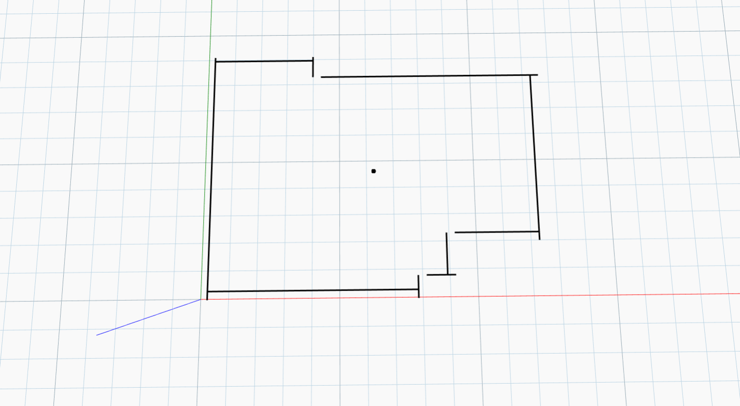
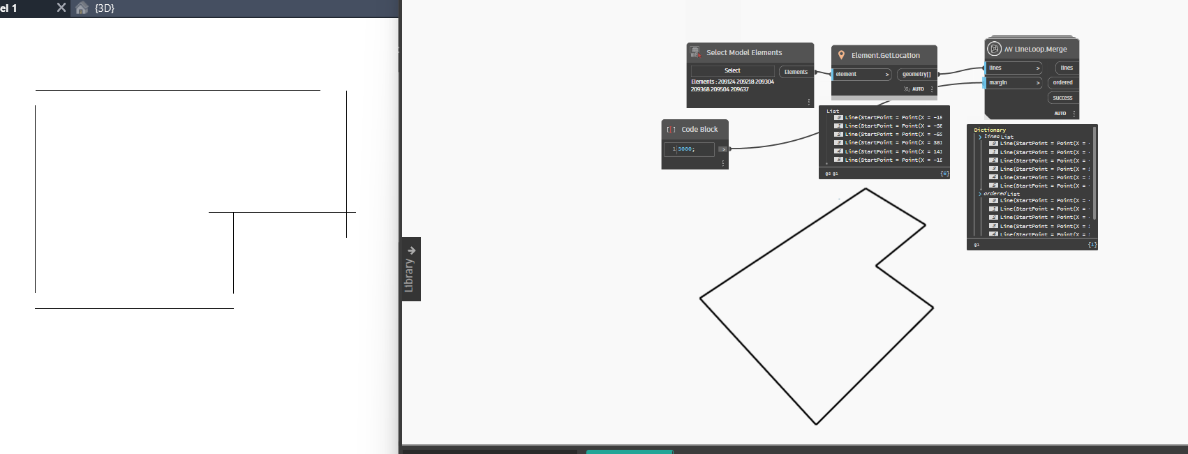
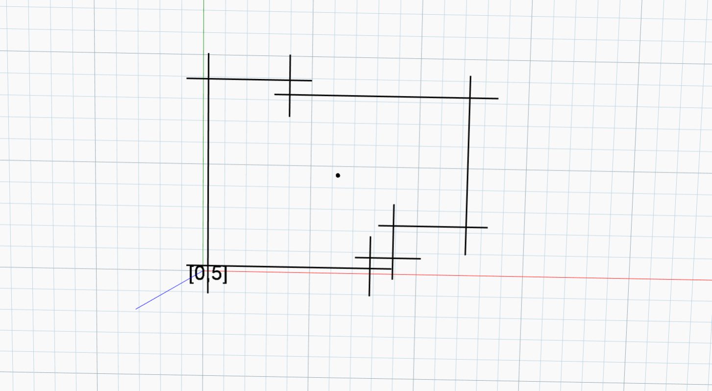
I’m working on a Dynamo model for Revit where I extract boundary curves (Lines and Arcs) from walls and floors to define compartmentation areas. I’ve already managed to get all the perimeter lines projected to a common Z level (like a floor plan). Now, I want to “fillet” or connect the corners where these lines meet.

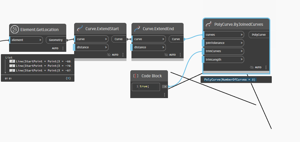
The challenge is that due to imprecise geometry, the ends of adjacent lines don’t always touch. I want to:

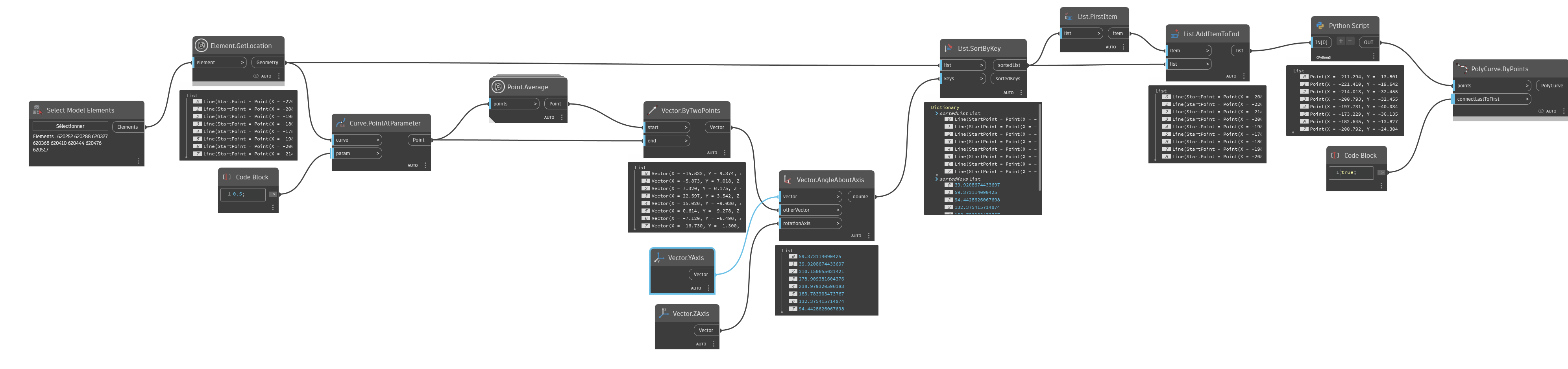
  • Sort the boundary curves into a continuous ordered loop (preferably clockwise),
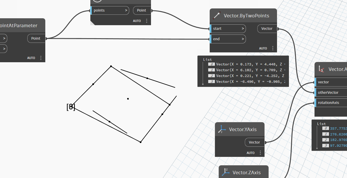
  • Identify gaps between endpoints
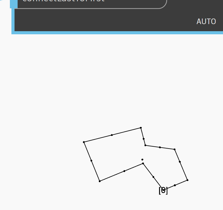
  • Extend the lines to meet at a common point (fillet with sharp 90º corners, not rounded),
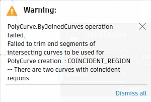
  • Avoid creating overlapping or duplicated lines,
  • Skip gaps if the lines clearly do not meet or are far apart.

Important notes:

  • I’m working only with 2D geometry (everything is planar),
  • Curves include both straight lines and arcs,
  • No openings expected outside of corners for now,
  • If the gap cannot be resolved reasonably, I just want to log a warning.

I’d prefer to do this with Dynamo nodes, but I’m open to Python solutions as well. I’m using packages like Clockwork, GeniusLoci, and Springs.

Thanks in advance for any help or suggestions!

Hello @flavi02000 and welcome to the forum, now you have spring installed you could try line merge…

1 Like

Hi, thanks for the suggestion! I tried applying that method, and while it seems to work in your image, in my case the resulting curves are exactly the same as the ones I already had, the gaps between the curves remain, and nothing gets joined or connected.

allright have you tried play with the margin ?

I tried 1, 100, 500, 3000, 10000, 15000 same result in all

hmm could you share small rvt sample with that situation

im sorry my ignorance but what you mean by that. i know that you are refering to a revit file

1 Like

yes exackly :wink: could you share that one…if you cant upload here then just upload to webtransfer, filetransfer etc.. and share the link here

Oh, sorry i really can’t do that because is my company property

ok I understand

hi
try this

Sincerely,
Christian.stan

Hi, thanks fo the sugestion
The PolyCurve.ByJoinedCurves gives me this error:

1 Like

Hi, try to extend it a little less than halfway.

Sincerely,
Christian.stan

Thanks for the suggestion! I tried using a value of 0.5 instead of 1, but I still get the same error on the PolyCurve.ByJoinedCurves node.

Also, I’m not entirely sure this method will work in all cases. Since my input lines don’t always touch , it’s hard to determine the correct distance value to make the fillets join properly without overextending or missing the corner entirely.

Any tips on how to make this more reliable across different geometries?

Thanks again!

Okay, I understand. I’m trying to find a more “one-size-fits-all” solution.
Sincerely,
Christian.stan

Geometry.ClosestPointTo, Curve.ParameterAtPoint, Curve.PointAtParamter, Curve.StartPoint and Line.ByStartPointEndPoint might help here.

The first to get the point on the next curve that is closest to the current curve.
The second to get the parameter of the original curve at which the found point sits.
The third to get the new end point of the curve.
The fourth to pull the start point of the new line.
The final to draw a new line though the points.

That sounds very helpful. Would you mind sharing a small example of how you’d set this up in Dynamo using those nodes? I think seeing how you’d connect them together would really help me understand how to approach this.

Appreciate it!

I won’t have time in the near future - give it a shot and see where you get. I promise it’s easier (and more fun) than it sounds. :slight_smile:

Here’s a potential solution by writing an equality at the intersection points of two successive lines.
I get inconsistent answers (I admit I don’t understand why) if the line’s orientation changes.
I’ll leave you the script and Python code if you’re interested in continuing down this path.

import sys
import clr
clr.AddReference('ProtoGeometry')
from Autodesk.DesignScript.Geometry import *
lin=IN[0]
def pint(l1,l2):
    a=(l1.StartPoint.Y - l1.EndPoint.Y)/(l1.StartPoint.X - l1.EndPoint.X)
    b=l1.StartPoint.Y-a*l1.StartPoint.X
    c=(l2.StartPoint.Y - l2.EndPoint.Y)/(l2.StartPoint.X - l2.EndPoint.X)
    d=l2.StartPoint.Y-c*l2.StartPoint.X
    return Point.ByCoordinates((d-b)/(a-c),a*(d-b)/(a-c)+b,l1.StartPoint.Z)

OUT = [pint(lin[i],lin[i+1]) for i in range(0,len(lin)-1)]

good


bad

Sincerely,
christian.stan
edit:
Hi, I modified Python node to handle a line parallel to the Y axis.

import sys
import clr
clr.AddReference('ProtoGeometry')
from Autodesk.DesignScript.Geometry import *
lin=IN[0]
def pint(l1,l2):
    if round((l1.EndPoint.X - l1.StartPoint.X),3)==0:
        c=round((l2.EndPoint.Y - l2.StartPoint.Y),5)/round((l2.EndPoint.X - l2.StartPoint.X),5)
        d=l2.StartPoint.Y-c*l2.StartPoint.X
        return Point.ByCoordinates(l1.StartPoint.X,c*(l1.StartPoint.X)+d,l1.StartPoint.Z)
    if round((l2.EndPoint.X - l2.StartPoint.X),3)==0:
        a=round((l1.EndPoint.Y - l1.StartPoint.Y),5)/round((l1.EndPoint.X - l1.StartPoint.X),5)
        b=l1.StartPoint.Y-a*l1.StartPoint.X
        return Point.ByCoordinates(l2.StartPoint.X,a*(l2.StartPoint.X)+b,l2.StartPoint.Z)
    else:
        a=round((l1.EndPoint.Y - l1.StartPoint.Y),5)/round((l1.EndPoint.X - l1.StartPoint.X),5)
        b=l1.StartPoint.Y-a*l1.StartPoint.X
        c=round((l2.EndPoint.Y - l2.StartPoint.Y),5)/round((l2.EndPoint.X - l2.StartPoint.X),5)
        d=l2.StartPoint.Y-c*l2.StartPoint.X
        return Point.ByCoordinates((d-b)/(a-c),a*(d-b)/(a-c)+b,l1.StartPoint.Z)


OUT = [pint(lin[i+1],lin[i]) for i in range(0,len(lin)-1)]

As long as the part remains convex, the center-of-point sorting procedure should work.

Otherwise, you have to select by pickorder (there are threads that discuss this).

Sincerely,
christian.stan
rep250417.dyn (26.7 KB)

4 Likes