I am trying to extract the exterior edge of a curtain wall and convert them to area boundaries on different levels.
I was trying to create planes at the respective levels of my model and see if I could intersect the curtain panel geometry and extract the curves, but I am hitting a block. I cannot find any nodes that seem to do this. I’m also not fluent in python yet.
Attached is a JPEG of the model in plan sketching out what I am trying to get.
Update, I was able to extrude the curves and boolean union them to make a solid. I am having trouble however deconstructing it with LunchBox Deconstruct Solid. Any ideas? Thank you.
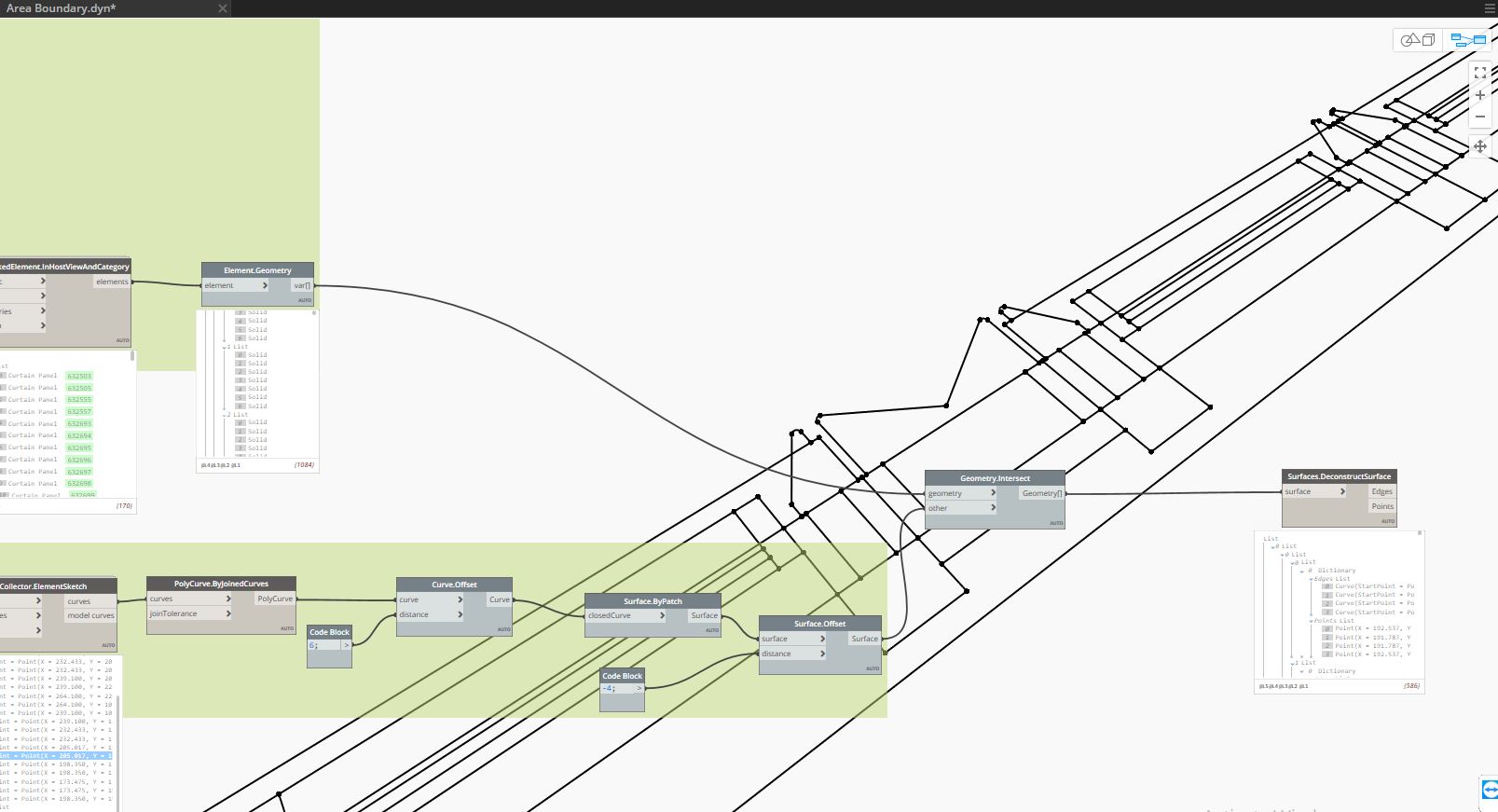
I was able to get the edges of the solid. I am not trying to join the curves into poly-curves and select the poly-curve with the longest length (the exterior edge). When I use the node PolyCurve.ByJoinedCurves I get an error that says:
Warning: PolyCurve.ByJoinedCurves operation failed.
Curve join produced more than one WIRE in PolyCurve
I don’t think you have to join the curves.
Just transfer them to Revit model lines in an area plan.
To get rid of the lines/outside on the inside, that’s another thing
sorry for that. i’m from Holland.
You can get the line direction and get the normal of a line and a vector from that.
But if an object is drawn is it always drawn clockwise or are you not sure on that?
I’m not sure if perimeter curves are Dynamo curves or Revit ones in this case
Then let me give you my thoughts.
Make a Room outside the building, confined with Room Separators away from the building, and get the contours of that Room.
Those are the Curves you want?
Thank you that sounds like a great strategy I will try it out. Just to clarify in this city calculating the zoning area is a particularly tedious act. The department of buildings wants the “edge” of the building to be the glass line of the curtain wall including any articulation within the mullions. Hence why I am trying to to get the outside exterior edge of the curtain wall as the area boundary.
You’re absolutely right. I’m sure that strategy would work. In my particular situation I am not the owner of the facade curtain wall nor it’s families. It is a model linked into my model. Typical coordination hell in an architecture office. I’m sure you’ve had your fair share. So I’m hoping to find a flexible workaround that can measure areas to the 200 or so different schemes we will inevitably try out during this process.
Ah! Well then same start point with a different twist:
In Revit make your initial area separation line at the location line of the curtain walls and place areas bound to those lines.
Select a curtain wall.
Then get all of the panels and mullions at your cut plane/floor line/wherever the AHJ indicates the area is calculated (they did this right? If not you could just use the interior face of the horizontal millions.) for the selected curtain wall.
Get the solids of the panels and millions and merge them into one solid.
Intersect the merged solid with the cut/measurement plane.
Create area separation lines for all of them. Yes, all of them.
Get the boundary lines of the area post creation (watch your transactions).
Filter out any non-bounding lines from the list of area separation lines created in step 5, and delete them.
Clear all file bindings and repeat 1-7 via Dynamo player for each CW in the file.
Thank you Jacob for the breakdown. I have successfully created an intersect. I am trying now to take the longer curve (the exterior) and place it in the view. My area separator node however has an error that says custom node not loaded.
Thank you, this may seem like a dumb question but how do i actually get the curves onto my specific view as area boundaries? What do i do with the output node of Area.Separator?