How were you able to convert pressure fittings and appurtenances to curves? I keep seeing examples with nodes that might be from the Civil3DToolkit, but that doesn’t seem to have it anymore. Was it removed?
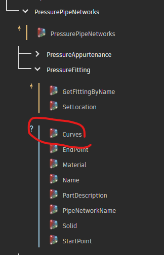
I can get curves of pressure pipes from the PressurePipe.Centerline2D or PressurePipe.Centerline3D. I don’t see anything for pressure fittings or appurtenances, though. How can I get get the curves of fittings & appurtenances?
It looks like my Civil3DToolkit is different than yours.
I’m using v1.1.32.
Almost all of those pressure part nodes are gone.
As a side note, I did not get any notification that you responded to my post. I just happened to look today at it and saw there was a reply.
Civil3D toolkit is not supported from 2025 and up, and will not be supported in the future.
Does that mean that there’s now no way to get curves from pressure fittings and appurtenances anymore?
Can’t say, burbI can say that Civil3D toolkit is not supported in modern Dynamo (3.0+) or Civil 3D builds.
@zachri.jensen might have a path forward.
So Autodesk created the Civil3DToolkit, integrated it to Dynamo without all of the nodes for C3D 2025+, then abandoned the Civil3DToolkit?

Paolo Serra created the toolkit, developed it, and provided it to the community. All of this was done in his own time, not as part of an Autodesk offering.
It was not officially part of the product or formal offering from Aurodesk.
Paolo kept it going for the community for far longer than he initially intended and he does not have time to continue releasing or maintaining it anymore. Prior to his moving on the tool the Civil 3D team indicated they planned on providing out of the box nodes / alternatives for anything Civil 3D related in the toolkit (which would include most nodes). Many such things have been added, however some things have slipped though the cracks.
I am not sure if pressure pipes are one of them, but these curves can be accessed in other ways.
Hi @Cadguru42,
There currently isn’t a direct way to get the geometry is this manner, so the best I can offer are workarounds.
You could try creating a plane at the location of each pressure part and then using Geometry.Intersect with the solid geometry to get the outlines. But if the expectation is for the result to match precisely with how the pressure part is currently shown based on its plan view style settings, then this approach won’t be robust.
The next option is to explode the entity and then create the geometry from the in-memory entities. This is likely the workaround that the node in the package was using.
Can you give a little more details about your end goal so I can understand the use case?
1 Like
My goal is to convert the pressure network to something that can be brought into ArcGIS. Autodesk doesn’t provide a way to do it out of the box, so I thought I’d try to use Dynamo to do it.
There was a post where someone did exactly what I want to do, but they used the nodes to get curves from the fittings & appurtenances that apparently have been discontinued.
Without a way to get the curves of the pressure fittings & appurtenances, there are gaps between the pipe curves. I just need flat curves with object data of centerline elevation at each end and inner diameter size. I don’t need a 3d solid of the network.
Posting a DWG and the Dynamo graph which works in 2024 would help.
Myself and likely others who might want to help would have to guess at the setup and might get it wrong otherwise.
I can’t post my drawing, but it doesn’t really matter. Any pressure network with pipes, fittings and appurtenances (some with offsets) would need to work. I am using C3D 2025 and C3D 2026.
I’ve been able to get the pressure pipe centerlines as curves easily with the PressurePipe.Centerline2D node. The problem is how to get a curve representing the fittings and appurtenances as well that fill in the gaps between the pipe curves. I don’t have a graph of that because those nodes apparently don’t exist anymore.
Thanks for the context. So is it a requirement to have the detailed geometry of the part, or would a simplified representation suffice? I ask because, if you are just using the centerlines of the pipes, then perhaps a box/rectangle for the parts might work.
I need a 2d (or 3d) curve (end result a polyline in Map3d/C3D) representing the centerline of the pipes, fittings and appurtenances with some object data, such as centerline elevation at each end and the size of the part.
If you need the detailed geometry for the parts, I would try something similar to this:
- Get the solids using
Object.Geometry
- Get the edges using
Topology.Edges and Edge.CurveGeometry
- Project the curves to the XY plane using
Curve.PullOntoPlane
- Join together using
PolyCurve.ByJoinedCurves
- Output to model space using
Object.ByGeometry
There will likely be some additional cleanup needed between 3 and 4.
If a rectangle will suffice, you could get the bounding box of the solids and then create a rectangle using the min and max points.
Does this method create a 2d curve (polyline) of the centerlines of the pipes, fittings, and appurtenances? I don’t need any 3d objects. Just centerlines in either 2d or 3d. It seems like your method is for creation of lines of the edge of the objects, not the centerline.
Yeah, my apologies. I assumed you were looking for something similar to what the old node from the package was doing, which (I believe) was generating the edges.
If that’s not what you need, then you could try just using the Object.Location node to get the insertion points of all the fittings/appurtenances and then “connect the dots” with a polycurve.
That won’t work as I need each segment to have its own data, including the fittings and appurtenances. I don’t need them joined, but do need each curve touching each other to represent the pipe, fitting, and appurtenance centerline.
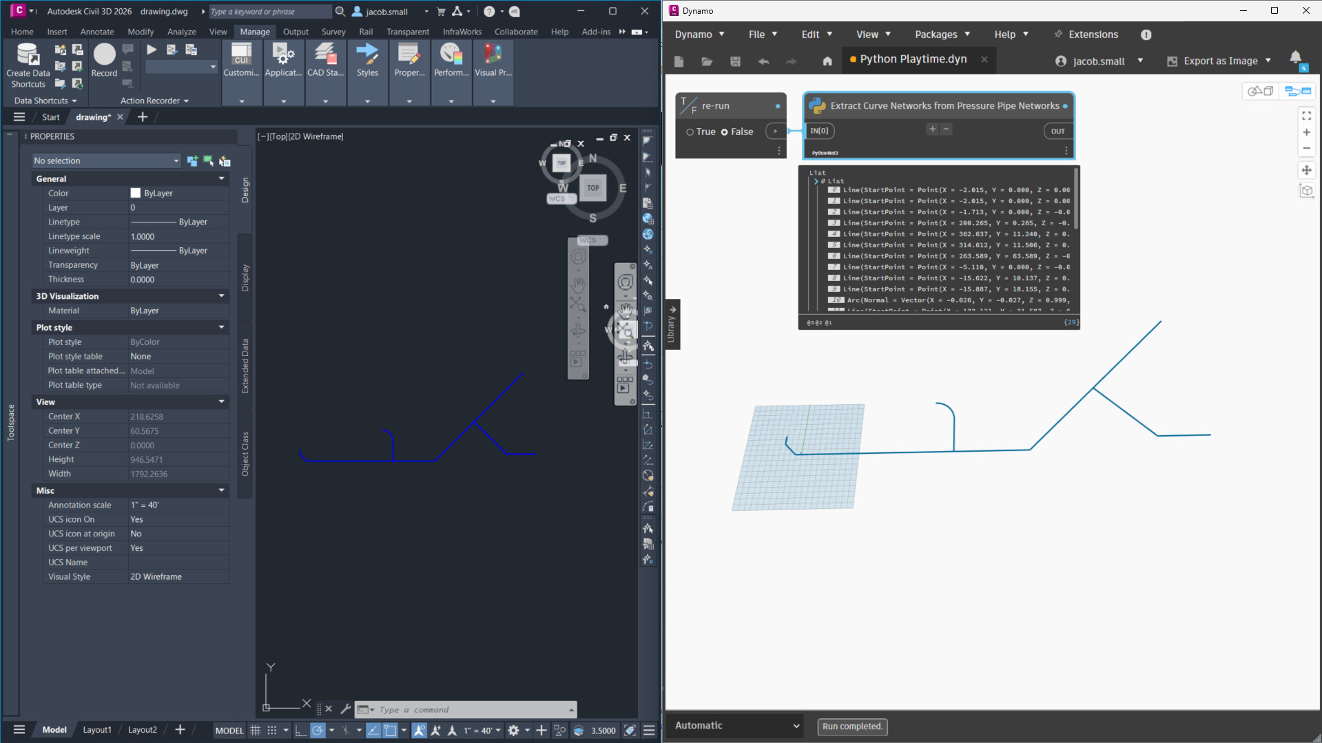
Here’s an example. The peach colored polylines are the pipes using the PressurePipe.Centerline2D node. The cyan are my manually created polylines representing the fittings and appurtenances that I’d like to get from Dynamo, but apparently cannot be done without a lot of programming. Just to get two polylines for a tee would require grabbing the tee, getting the center point (easy), grabbing the connecting parts end points, then creating curves between those points. Not sure how to tell it to join the pass-through lines and not the branch.
What’s frustrating is that the linework for the centerlines is in the drawing data already. C3D can style the pipes, fittings and appurtenances as centerlines, but apparently Dynamo can’t get that linework for fittings and appurtenances and keep the data with it.
Thanks for the screenshot, that helps clarify. For the result to match the plan view style behavior, your best option is going to be exploding everything down and getting the geometry that way. A Python script or custom node would be necessary here.
It is still possible to achieve this by going directly to the Civil 3D API, which you can still do through Dynamo. But you are correct that currently there is not a dedicated node for this. We add nodes for specific workflows that come up as being high priority and beneficial to a lot of users, and this particular use case just hasn’t come up until now. But I have added it to our backlog for future improvement 
2 Likes
The Python below will extract the curve network for all pressure pipe networks in the active document. I’ve used the PythonNet3 engine in Civil 3d 2026; it may or may not work with the default CPython3 engine and Civil 3d 2025. The network I built had as many conditions to test as I could think of, but it might fail with any I didn’t think to test so it might not be complete (why I was requesting the DWG before). The code is quite thoroughly annotated so it should give you a starting point which you can make changes to suit your needs.
results:
The Python Code
########################################
############## Properties ##############
########################################
__author__ = 'Jacob Small'
__version__ = '0.1.0'
__description__ = "Extracts the curve network for pressure pipe systems in the active DWG"
__DynamoBuilds__ = "Dynamo for Civil 3D 3.4"
__ReleaseNotes__ = "POC only, not for production work."
__Dependancies__ = "none"
__Copyright__ = "2025, Autodesk Inc."
__license__ = "Apache 2"


########################################
### Configure the Python environment ###
########################################
### standard imports ###
import sys #add the sys class to the Python environment so we can work with the sys objects
import clr #add the CLR (common language runtime) class to the Python environment so we can work with .net libraries

### basic Dynamo imports ###
clr.AddReference('ProtoGeometry') #add the Dynamo geometry library to the CLR
from Autodesk.DesignScript import Geometry as DG #add the Dynamo geometry class using the alias DG, to ensure no overlap between class calls in Revit or Dynamo

### AutoCAD API imports ###
clr.AddReference('AcMgd') #add the autocad application API to the CLR
clr.AddReference('AcCoreMgd') #add the autocad core API to the CLR
clr.AddReference('AcDbMgd') #add the autocad DB api to the CLR
from Autodesk.AutoCAD.Runtime import * #import the autocad application API to the Python environment
from Autodesk.AutoCAD.ApplicationServices import * #import the autocad application services API to the Python environment
from Autodesk.AutoCAD.EditorInput import * #import the autocad editor API to the Python environment
from Autodesk.AutoCAD.DatabaseServices import * #add the autocad DB API to the Python envrionment
from Autodesk.AutoCAD.Geometry import * #add the autocad geometry API to the Python environment

### Civil 3D API imports ###
clr.AddReference('AecBaseMgd') #add the civil 3D base API to the CLR
clr.AddReference('AecPropDataMgd') #add the civil 3d property sets API to the CLR
clr.AddReference('AeccDbMgd') #add the civil 3d DB API to the CLR
# Import references from Civil3D
from Autodesk.Civil.ApplicationServices import * #add the Civil 3D application services API to the Python environment
from Autodesk.Civil.DatabaseServices import * #add the Civil 3D DB API to the Python environment


#########################################
###### Global variables and inputs ######
#########################################
### documents and standard variables ###
run = IN[0] #input to trigger re-execution
adoc = Application.DocumentManager.MdiActiveDocument #the active document
adoc.LockDocument(DocumentLockMode.Read, None, None, False) #lock the document
db = adoc.Database #get the database
transactionManager = db.TransactionManager #get the transaction manager
transaction = transactionManager.StartTransaction() #start a new transaction
blockTable = transaction.GetObject(db.BlockTableId, OpenMode.ForRead) #open the block table
blockTableRecord = transaction.GetObject(blockTable[BlockTableRecord.ModelSpace], OpenMode.ForRead) #get the block table records in model space
allObjects = [transaction.GetObject(objectId, OpenMode.ForRead) for objectId in blockTableRecord] #get all objects in model space
pressurePipeNetworks = [i for i in allObjects if i.__class__ == PressurePipeNetwork ] #get the pipe networks in model space
results = [] #empty list to hold the results


#########################################
############ Code goes here #############
#########################################
for pressurePipeNetwork in pressurePipeNetworks: #for each found pipe network
    objects ={"appurtenances":[], "appurtenance_Curves": [], "pipes": [], "pipe_Curves": [], "fittings": [], "fitting_Curves": []} #dictionary to store objects and curves - useful for debugging
    curveNetwork = [] #list to store curves which are found in the curve network
    #process the appurtenances
    appurtenances =  [transaction.GetObject(i, OpenMode.ForRead) for i in pressurePipeNetwork.GetAppurtenanceIds()] #get the appurtenances from the pipe network
    [objects["appurtenances"].append(i) for i in appurtenances] #append the appurtenances to the objects dictionary
    for appurtenance in appurtenances: #for each of the appurtenances
        crvSet = [] #empty list to hold the curves
        basePoint = appurtenance.Position #get the base point
        basePoint = DG.Point.ByCoordinates(basePoint.X,basePoint.Y) #convert the base point to Dynamo geometry
        connectionCount = appurtenance.ConnectionCount #get the number of connections in the appurtenance
        for i in range(connectionCount): #for each index of the range of connections
            connection = appurtenance.GetConnectionAt(i) #get the connection at the index
            connectionLocation = connection.Position #get the location of the connection
            connectionLocation = DG.Point.ByCoordinates(connectionLocation.X, connectionLocation.Y, connectionLocation.Z) #connvert the connection location to a dynamo point
            connectionCurve = DG.Line.ByStartPointEndPoint(basePoint,connectionLocation) #build a line from the connection to the base
            crvSet.append(connectionCurve) #append the line to the curve set
            curveNetwork.append(connectionCurve) #append the line to the curve network
        objects["appurtenance_Curves"].append(crvSet) #append the curve set to the list of appurtenance curves
    #process the pipes
    pipes = [transaction.GetObject(i, OpenMode.ForRead) for i in pressurePipeNetwork.GetPipeIds()]#get the pipes from the pipe network
    [objects["pipes"].append(i) for i in pipes] #append the pipes to the objects dictionary
    for pipe in pipes: #for each pipe
        start = pipe.StartPoint #get the start point
        start = DG.Point.ByCoordinates(start.X,start.Y,start.Z) #convert the start point to a Dynamo point
        end = pipe.EndPoint #get the end point
        end = DG.Point.ByCoordinates(end.X, end.Y, end.Z) #convert the end point to a Dynamo point
        if pipe.IsCurve: #if the pipe is curved
            cent = pipe.CenterPointLocation #get the center point of the arc
            cent = DG.Point.ByCoordinates(cent.X, cent.Y, cent.Z) #convert the center point to a Dynamo point
            curve = DG.Arc.ByCenterPointStartPointEndPoint(cent, start, end) #get the primary curve as a dynamo arc
            altCrv = DG.Arc.ByCenterPointStartPointEndPoint(cent, end, start) #get the reverse curve as a Dynamo arc
            arcLength = pipe.Length3DCenterToCenter  #get the arch length of the Autocad curve
            if abs(curve.Length-arcLength) > abs(altCrv.Length-arcLength): curve = altCrv #if the alternative curve is closer in length to the autocad curve than then primary curve, set the primary curve to the alternative

        else: #if the pipe is not curved
            curve = DG.Line.ByStartPointEndPoint(start, end) #set the curve to the line from the start to the end
        objects["pipe_Curves"].append(curve) #append the pipe curves
        curveNetwork.append(curve) #append the curve to the curve network
    #process the fittings
    fittings = [transaction.GetObject(i, OpenMode.ForRead) for i in  pressurePipeNetwork.GetFittingIds()] #ge the fittings from the pressure pipe network
    [objects["fittings"].append(i) for i in fittings] #append the fittings to the objects dictionary
    for fitting in fittings: #for each fitting
        crvSet = [] #empty list for the curve set
        basePoint = fitting.Position #get the base point
        basePoint = DG.Point.ByCoordinates(basePoint.X,basePoint.Y) #convert the base point to a Dynamo point
        connectionCount = fitting.ConnectionCount #get the number of connections in the fitting
        for i in range(connectionCount): #for each index in the range of connections
            connection = fitting.GetConnectionAt(i) #get the connection at the index
            connectionLocation = connection.Position #get the location of the connection
            connectionLocation = DG.Point.ByCoordinates(connectionLocation.X, connectionLocation.Y, connectionLocation.Z) #convert the location to a Dyanmo point
            connectionCurve = DG.Line.ByStartPointEndPoint(basePoint,connectionLocation) #build a line from the connection to the base
            crvSet.append(connectionCurve) #append the line to the curve set
            curveNetwork.append(connectionCurve) #append the line to the curve network
        objects["fitting_Curves"].append(crvSet) #append the curve set to the list of fitting curves
    results.append(curveNetwork) #append the curve network to the results list
transaction.Abort() #abort the transaction as no changes were made


#########################################
##### Return the results to Dynamo ######
#########################################
OUT = results
1 Like